
- Introduction
- Magnetic Effect of an Electric Current Flowing Through a Conductor (Oersted’s Experiment)
- Magnetic Field Patterns on a Straight Current Carrying Conductor (Fleming’s Right Hand Grip Rule)
- Magnetic Field on a Current Carrying Solenoid
- Simple Electromagnet
- Force on a Current Carrying Conductor (The Motor Effect)
- Applications of Magnetic Effect of an Electric Current
- Revision Exercise

Introduction
- This topic involves the study of magnetic field due to the flow of electric current in a conductor and the applications of this effect.
- The pioneer of this physics topic is Hans Oersted, a professor of physics.
Magnetic Effect of an Electric Current Flowing Through a Conductor (Oersted’s Experiment)
- Consider the diagram below of a set up that can be used to investigate the magnetic effect of an electric current flowing through a conductor.
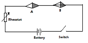
- This is commonly called Oersted’s experiment.
- A and B are magnetic compass needles.
- When the switch is closed, it is observed that the compass needles deflect towards the directions shown in the diagram below.
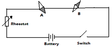
- The direction of deflection of the compass needles can be predicted by Ampere’s swimming rule which states that“if one imagines swimming along a conductor in the direction of electric current and facing the compass needle, then the north pole of the needle will be deflected towards the swimmer’s left hand”
Notes:
- The deflection of the compass needles is due to the interaction between the magnetic field due to the electric current in the conductor and the magnetic field of the compass needle.
- When the terminals of the battery are interchanged, the compass needles deflect in the opposite direction because the direction of current reverses.
- The extent of deflection of the compass needles increases when the amount of electric current flowing through the conductor increases.
Exercise
The figure below shows a compass placed under a vertical wire XY.
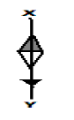
A large current is passed from X to Y. Draw the position of the magnetic compass needle.
Magnetic Field Patterns on a Straight Current Carrying Conductor (Fleming’s Right Hand Grip Rule)
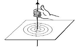
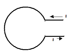
- When a large electric current flows through a wire passing through a card board on which iron filings is sprinkled, the filings form a pattern of concentric circles around the wire as shown below.
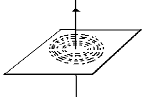
- This behavior of iron filings show that the magnetic field around a straight current carrying conductor forms a pattern of concentric circles and is perpendicular to the conductor.
- The direction of this magnetic field pattern can be predicted by Fleming’s right hand grip rule for a current carrying straight conductor which states that “if a current carrying conductor is gripped in the right hand with the thumb pointing along the wire in the direction of current, the other fingers will point in the direction of the magnetic field”.
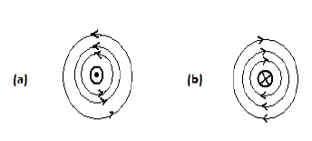
- Note:The cross symbol represents current into the surface and dot symbol current out of the surface.
Magnetic Field on a Current Carrying Solenoid
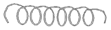
- A solenoid refers to a wire wound into a long cylindrical coil with many connected loops.
- Fleming’s right hand grip rule for a current carrying solenoid is used to predict the direction of magnetic field pattern inside the solenoid due to the current.
- It states that “If a coil carrying electric current is held in the right hand such that the fingers encircle the loops while pointing in the direction of current flow, the thumb points in the direction of the North Pole”
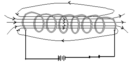
- Note that a solenoid carrying electric current produces a magnet field pattern like that of a bar magnet; one end behaves North Pole and the other end South Pole.
Exercise
Show the magnetic field pattern inside the loop below
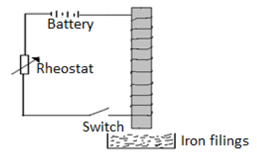
Simple Electromagnet
- An electro magnet is made by placing a soft iron core inside a solenoid carrying an electric current. This is shown below.
- The right hand grip rule for a current carrying solenoid can as well be used to predict the polarities of the electromagnet.
Factors Affecting the Strength of an Electromagnet
- The amount(size) of current in the solenoid– the strength of an electromagnet is directly proportional to the amount of electric current in the solenoid. Therefore, the larger the current, the strong the electromagnet.
- The number of turns in the solenoid– the strength of the electro magnet is directly proportional to the number of turns in the solenoid. Therefore, the more the number of turns the strong the electromagnet.
- The length of the solenoid– the strength of the electro magnet is directly proportional the length of the solenoid. Therefore the longer the solenoid the stronger the electromagnet.
- The shape of the core - horse-shoe shaped core produces a stronger electromagnet than u-shaped core while a u-shaped core produces a stronger electro magnet than a straight core.
Exercise
- In the diagram below the soft iron core is placed inside a coil connected to a d.c source.
End B was brought near the iron filings and many of them were attracted when the switch was closed.- Explain why the iron filings got attracted at end of the core.
- Explain what is observed when the switch is opened.
- If soft iron was replaced with steel and switch closed:State what is observed when steel is brought near iron filings
- Mention three differences between soft iron and steel as illustrated in the above experiment.
- Explain what happens if steel is replaced with copper and dipped in the iron filings.
- The diagram below shows a wire wound on an open pipe at both ends. The wire is then connected to a d.c supply. The north pole of a magnet is near the end of the core B.
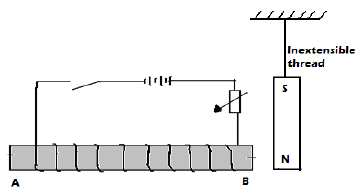
- What is observed at the magnet when the switch is closed?
- Explain the observation in the question above.
- If the terminals of the cells are reversed state what is observed on the magnets.
- What name of making a magnet is illustrated in the above arrangement?
- What are the two advantages of this method over other methods of magnetization?
- In an experiment to determine the strength of an electromagnet, the weight of pins that can be supported by the electromagnet, was recorded against the number of turns. The current was kept constant throughout the experiment. The table below shows the data that was obtained.
Number of turns, n, 0 4 8 12 16 20 24 28 32 36 Weight, W, of pins x 10-3 (N) 0 4 14 30 58 108 198 264 296 300 - Plot a graph of weight, W, against number of turns, n.
- Use the domain theory to explain the nature of the graph
- Sketch on the same axes the curve that will be obtained using a higher current.
Force on a Current Carrying Conductor (The Motor Effect)
- A conductor carrying current placed in a magnetic field experiences a force. This is called the motor effect.
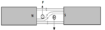
- Consider the setup diagram below for a conductor carrying current in a magnetic field.

- The magnetic field concentrates at the top of the conductor than at the bottom thereby creating a region of strong field. The reason for this is that the field due to electric current in the conductor and that of the magnets reinforce each other since they are directed in the same direction.
- The relatively weak field at the bottom of the conductor is as a result of cancellation between the two fields since they are directed in opposite directions. The resultant force therefore acts on the conductor downwards.
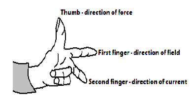
- The direction of force on conductor can be predicted by Fleming’s left hand rule which states that “If the thumb, first and second fingers are held mutually at right angles with the first finger pointing the direction of magnetic field, the second finger in the direction of current, then the thumb points in the direction of force”
Exercise
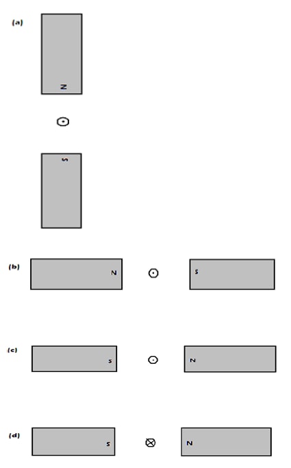
Show the resultant magnetic field and direction of force of the conductor in each of the following.
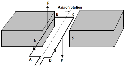
- For rectangular coil in a magnetic field, one side experiences an upward force and the other side a downward force and the coil is set into a rotation. Below is an example.
Force between Parallel Straight Current Carrying Conductors
a. Parallel Conductors Carrying Current in Same Direction
- The magnetic field between the conductors is weaker due to cancellation than the field from the outer side.
- The resultant force on the conductors acts to push them towards each other.
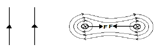
b. Parallel Conductors Carrying Current In Opposite Direction
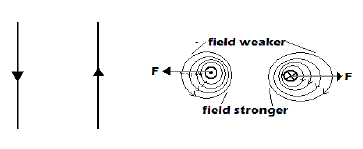
- The fields between the conductors repel each other since they are directed in same direction.
- A force, therefore, acts on the conductors to pull them apart (outwards)
Factors Affecting Force on a Conductor Carrying Current in a Magnetic Field
- Magnitude of electric current- force increases with current.
- Strength of magnetic field– force increases with strength of the magnetic field
- Length of the conductor in the field– the longer the length the stronger the force
- Angle the conductor makes with the magnetic field– force increases with the angle. It is maximum when the conductor is at an angle of 900 with the magnetic field
Exercise
- The figure below shows a rectangular coil PQRS of many turns of wire located in a magnetic field due to two poles north and south. The coil is free to rotate on the vertical axis CD.
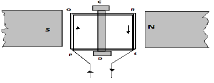
When a current is passed through the coil in the direction PQRS the coil starts to turn, and eventually comes to rest. With the aid of diagrams explain:- Why the coil begins to turn
- In which direction it begins to turn
- Why it comes to rest
- The position in which it comes to rest
- The apparatus shown below may be used to cause rider AB move along the rods C and D
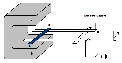
- When current flows along AB, in what direction will it roll? Explain.
- What happens to the rider when current is increased?
- State the rule that can be used to predict the direction of force acting on the rider.
Applications of Magnetic Effect of an Electric Current
1. Electric Bell
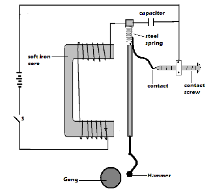
- The capacitor is used to reduce sparking effect at the contacts.
- The circuit is completed at the contact spring and contact screw.
Working Mechanism of an Electric Bell
- When current is switched on, it flows through the circuit and the soft iron core becomes magnetized.
- The magnetized iron core then attracts the sot iron armature, which has a hammer at its end.
- On attraction, the hammer knocks the gong and the bell rings.
- When the soft iron armature is attracted, the contact at the contact screw is broken and current stops flowing.
- The electromagnet loses its magnetism and releases the soft iron armature and this closes the contact again.
- This process is repeated and the bell rings continuously as long as the switch is closed.
2. Electric Motor
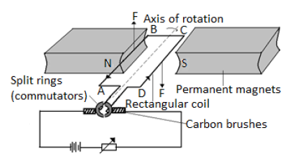
- It is a devise which converts electrical energy into rotational kinetic energy.
- The permanent magnets are curved at the ends to produce radial magnetic field.
Functions of Carbon Brush
- Presses lightly against the commutators so that the coil rotates freely and easily.
- Connect the coil to the electric current source.
Reasons why carbon brushes and commutators are made of graphite
- Graphite is a good conductor of electricity.
- It serves as a lubricant since it is slippery.
Working Mechanism of the Electric Motor
- When the coilis horizontal and current passes through it as shown on the diagram, side AB experiences an upward force while BC experiences a downward force.
- The two forces make the coil rotate in the clockwise direction.
- When the coil is in the vertical position with AB at the top and CD at the bottom, the brushes touch the spaces between the two split rings.
- Due to momentum, the coil continues to rotate and the commutators interchange the contact positions with the brushes.
- The current is then reversed in the coil and the forces acting on each side reverse in direction. Side AB is now on the right with a downward force while side CD is on the left with an upward force.
- The coil continues to rotate.
3. Simple Magnetic Relay
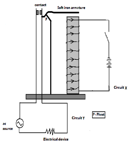
- In a magnetic relay, one circuit is used to control another circuit without any direct electrical connection between them.
Working Mechanism of Magnetic Relay
- When the switch is closed, current flows through circuit X; electromagnet is made on the solenoid and in turn attracts the soft iron armature.
- This closes the contacts in circuit Y.
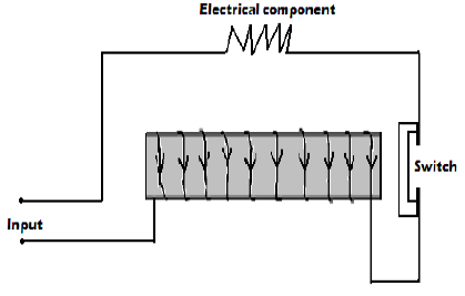
4. Circuit Breakers
- Circuit breakers are used to protect electrical components from excessive flow of current.
Working Mechanism of a Circuit Breaker
- When excess current flows through the circuit, increased magnetic power of the electromagnet opens the switch, thus stopping current flow.
Revision Exercise
- State two factors that affect strength of an electromagnet
- In the setup below, the suspended meter rule is balanced by the magnet and the weight shown. The iron core is fixed on the bench.
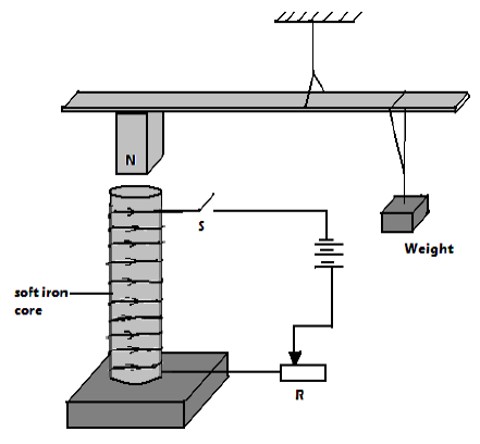
- State and explain the effect on the meter rule when the switch is closed.
- What would be the effect of reversing the battery terminals?
- Suggest how the setup in the figure can be adopted to measure the current flowing in the current circuit.
Join our whatsapp group for latest updates
Tap Here to Download for 50/-
Get on WhatsApp for 50/-
Download MAGNETIC EFFECT OF AN ELECTRIC CURRENT - Form 2 Physics Notes.
Tap Here to Download for 50/-
Get on WhatsApp for 50/-
Why download?
- ✔ To read offline at any time.
- ✔ To Print at your convenience
- ✔ Share Easily with Friends / Students