

How to Use an Ammeter and Voltmeter
- Connect the positive terminal of the ammeter/ voltmeter to the positive terminal of the battery.
- Ensure that the pointer is initially at zero i.e. there is no zero error. If there is a zero error, correct it before using the instrument.
- Select an appropriate scale to use.
- Avoid parallax error taking readings i.e. view the scale normally.
Ohm’s Law
- This law relates the current flowing through a conductor and the voltage drop across that section of the conductor.
- The law states: the current flowing through a conductor is directly proportional to the potential difference across its ends provided temperature and other physical factors are kept constant .
- The following set up can be used to investigate Ohm’s law:
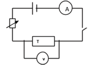
- Close the switch and adjust the current flowing through the conductor T using the rheostat to the least possible value. Record the corresponding voltmeter reading.
- Increase the current in steps recording the corresponding voltmeter readings. Record your values in the table below
Current I (A) Voltage V (V) - Plot a graph of voltage against current. Hence determine the slope of the graph.
- A graph of voltage against current is a straight line through the origin. Hence voltage drop across the conductor is directly proportional to the current through it;

V α I
V/I = constant - The constant is known as resistance R of the conductor T under investigation.
Thus, V/I= R
Or V= IR. - Hence the slope of a voltage—current graph is equal to the resistance R of the conductor T.
- Electrical resistance can be defined as the opposition offered by a conductor to the flow of electric current. It is measured using an ohmmeter.
- The SI Unit of electrical resistance is the ohm (Ω). Other units include kilo-ohm (kΩ) and mega-ohm (MΩ);
1Ω= 10-3 kΩ
1Ω= 10-6 MΩ - Materials which obey Ohm’s law are said to be ohmic materials while those which do not obey the law are said to be non-ohmic materials.
- The graph of voltage against current for non-ohmic materials is a curve or may be a straight line but does not pass through the origin.
- The inverse on resistance is called conductance;
Conductance= 1/resistance R.
Example 5.3
- Calculate the current flowing through a 8Ω device when it is connected to a 12V supply.
I= V/R
I= 12V/8Ω =1.5A
Factors Affecting the Resistance of a Conductor
- There are three main factors that affect the resistance of a conductor:
- Temperature
Increase in temperature enhances the vibration of the atoms and thus higher resistance to the flow of current. - Length of the conductor L
The resistance of a uniform conductor increases with increase in length. - Cross section area A
A conductor having a wider cross section area has more free electrons per unit length compared to a thin one.
Hence a thicker material has a better conductivity than a thinner one. Generally, resistance varies inversely as the cross section area of the material.
- Temperature
- Therefore, at a constant temperature resistance varies directly as the length and inversely as the cross section area of the conductor;
R α L/A
R= (A constant × L/A)
Or simply, AR/L= constant
The constant is called the resistivity of the material;
Resistivity ϱ= (cross section area A × resistance R)/length L.
Resistivity is measured in ohm-metre (Ωm).
Example 5.4
- A wire of resistance 3.5Ω has a length of 0.5m and cross section area 6.2 × 2 -8 m 5. Determine its resistivity.
Resistivity ϱ= AR/L = (6.2 × 10⁻⁸m2 × 3.5Ω)/0.5m
= 5.74 × 10⁻⁷ Ωm - Two conductors A and B are such that the cross section area of A is twice that of B and the length of B is twice that of A. If the two are made from the same material, determine the ratio of the resistance of A to that of B.
R=ϱL/A
Therefore, RA = ϱALA/AA
And RB = ϱBLB/AB
Where LB =2LA
AB = 1/2AA
And ϱA = ϱB
Hence RA =ϱALA/AA and RB = 2ϱALA/0.5AA = 4ϱALA/AA
Thus RA /RB =ϱALA/AA = 1/4
4ϱALA /AA
RA : RB = 1 : 4
Resistors
- A resistor is a specially designed conductor that offers a particular resistance to the flow of electric current.
- There are three main groups of resistors:
- Fixed resistors- offer fixed values of resistance. They have colour bands around them.
- Variable resistors- offer varying resistance e.g rheostat and potentiometer.
- Non-linear resistors- the current flowing through these resistors does not change linearly with the voltage applied. Examples include a thermistor and light-dependent resistor (LDR).
Measurement of resistance
- Three methods may be used:
- Voltmeter- ammeter method
- In this method, the current flowing through the material and voltage across its ends are measured and a graph of voltage against current plotted.
- The slope of the graph gives the resistance offered by the material.
- The wheatstone bridge method
- A wheatstone bridge consists of four resistors and a galvanometer connected as shown below:
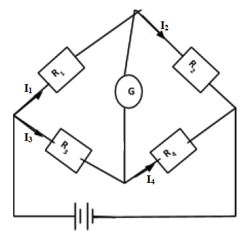
- The values of three out of the four resistors must be known.
- The value of one of the resistors is adjusted to a point that the galvanometer does not deflect. At this point, the voltage drop across R1 is equal to that across R3
- Similarly, the voltage drop across R2 is equal to that across R1.
- Note that the current flowing through R2 is equal that through R4. Also, the current through R3 is the same to that through R1.
Therefore, I1R1 = I2R3 …………………………. (i)
I1R2 = I2R4 …………………………. (ii)
Dividing equation (i) by (ii), we get;
R1/R2 = R3/R4 - This method is more accurate compared to the voltmeter - ammeter method since the voltmeter has some resistance against the flow of current and thus takes up some voltage.
- A wheatstone bridge consists of four resistors and a galvanometer connected as shown below:
- The metre bridge method
- This method relies on the fact that resistance is directly proportional to the length of the conductor.
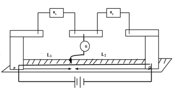
- The values of R1 and R2 must be known.
- Suppose at point K the galvanometer does not deflect, then the voltage drop across R1 equal the voltage drop across the section L1 .
- Similarly, the voltage drop across R 2 equals the voltage drop across the section L 5.
- If the current through R 1 and R 2 is I 1 and that through the section L1 and L2 is I2 , then;
I1R1 = I2L1 ………………………….. (i)
I1R 2 = I2L2 …………………………… (ii)
Dividing equation (i) by (ii), we get;
R1/R2 = L1/L2
- This method relies on the fact that resistance is directly proportional to the length of the conductor.
- Voltmeter- ammeter method
Example 5.5
- In an experiment to determine the resistance of a nichrome wire using the metre bridge, the balance point was found to be at the 40cm mark. Given that the value of the resistor to the right is 30Ω, calculate the value of the unknown resistor R.
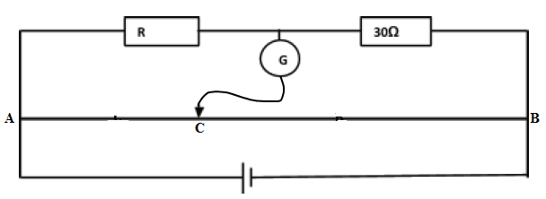
LAC /LCB = R/30Ω
40cm/60cm = R/30Ω
R= (30×40)/60 = 20Ω
Resistor networks
Series network
- When resistors are arranged in series the same current pass through each one of them.
- Consider three resistors connected as shown below:
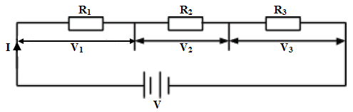
From Ohm’s law, V= IR.
The voltage drop across R1; V1 = IR1
The voltage drop across R2; V2 = IR2
The voltage drop across R3; V3 = IR3
And the total circuit voltage V= V1 +V2 +V3 .
Thus V = IR1 +IR2 +IR3 =I(R1 +R2 +R3)
V/I =(R1 + R2 + R3 )
But V/I = R
Thus the combined circuit resistance R = R1 +R2 + R3 . - Generally, the effective resistance of resistors arranged in series is equal to the sum of the individual resistances.
Parallel network
- When resistors are connected in parallel, the same voltage is dropped across them.
- Consider three resistors connected as shown below:
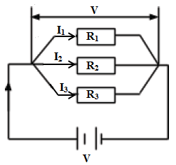
- Suppose the current flowing through R 1 is I1 , through R2 is I2 and through R3 is I3 then:
The voltage drop across R1; V1 = I1R1
The voltage drop across R2; V2 = I2R2
The voltage drop across R3; V3 =I3R3
But V1 = V2 = V3 = V and I = I1 +I2 +I3
Therefore, I=V/R1 + V/R2 + V/R3
I/V = (1/R1 + 1/R2 + 1/R3)
But I/V= 1/R.
Hence 1/R= 1/R1 + 1/R2 + 1/R3
R is the combined circuit resistance. - Special case of two resistors in parallel
It follows that 1/R= 1/R1 +1/R2
1/R= (R1 + R2 )/R1R2
Hence the effective resistance R= R1R2/(R1 + R2). - Generally for n resistors arranged in parallel, the effective resistance of the arrangement is given by;
1/R=1/R1 + 1/R2 +…………..+1/Rn - NOTE: when a circuit comprise of both series and parallel connections, the arrangement is systematically reduced to a single resistor.
Example 5.6
- The figure below shows 3 resistors.
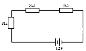
Calculate:- The effective resistance of the circuit.
R= (8+5+3)Ω = 3Ω - The total current in the circuit.
I=V/R = 12V/3Ω = 0.75A - The voltage drop across each resistor.
V8Ω = 0.75 × 8 = 5.0V
V5Ω = 0.75 × 5 = 3.75V
V3Ω =0.75 × 3 = 5.25V
- The effective resistance of the circuit.
- Three resistors are connected as shown below:
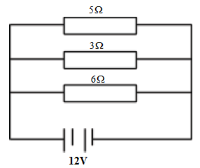
Calculate:- The total resistance of the circuit.
1/R= 1/5 + 1/3 + 1/6
1/R= (6+2+5)/30 =21/30
R= 30/21 = 1.4286Ω - The current through each resistor.
I5Ω =12V/5Ω=5.4A
I3Ω =12V/3Ω=1.0A
I6Ω =12V/6Ω=5.0A
- The total resistance of the circuit.
- The figure below shows five resistors and 6.0V supply.
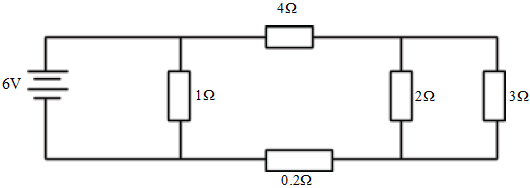
Calculate:- The effective resistance of the circuit.
R2,3Ω =(2×3)/(2+3) = 1.2Ω
R4,1.2,0.2Ω =4 + 1.2+0.2 =5.4Ω
R= R1,5.4Ω =(1×5.4)/(1+5.4) = 0.8438Ω - The total circuit current.
I=V/R = 6V/0.8438Ω =3.127A
- The effective resistance of the circuit.
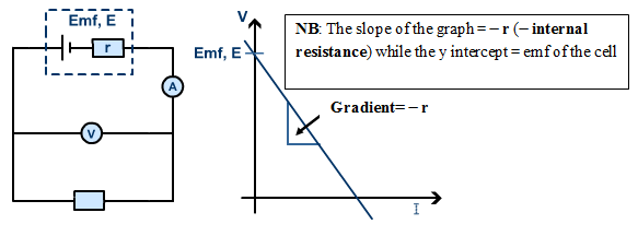
Internal Resistance r
- When a cell supplies current in a circuit, the potential difference between its terminals is observed to be lower than its electromotive force (emf).
- This difference is due to the internal resistance of the cell.
- Some work must be done to overcome this resistance and so the drop in the emf of the cell is responsible for this.
- The difference is referred to as the lost volt and is given by Ir.
i.e. lost volts = emf − terminal voltage
Or simply emf = terminal voltage + lost volts - The mathematical equation connecting emf, circuit current, external resistance and internal resistance of the cell is given by:
E= IR + Ir= I(R+r). - Internal resistance of a cell can be obtained experimentally. In such an experiment, the following data was obtained:
Current I (A) 0.1 0.2 0.3 0.4 0.6 0.8 Volatge V (V) 1.43 1.30 1.4 1.09 0.82 0.58 - When a graph of Voltage V against current I is plotted, the graph will appear as shown below:
Join our whatsapp group for latest updates
Tap Here to Download for 50/-
Get on WhatsApp for 50/-
Download CURRENT ELECTRICITY - Form 3 Physics Notes.
Tap Here to Download for 50/-
Get on WhatsApp for 50/-
Why download?
- ✔ To read offline at any time.
- ✔ To Print at your convenience
- ✔ Share Easily with Friends / Students