
SECTION A (25 Marks)
Answer all the questions in this section
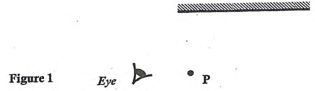
- Figure 1 shows a plane mirror, a point object (P) and the position of the observer's eye. Show whether the observer will see the image of the object point P or not. (1 mark)
- State one difference between a lead-acid battery cell and a Leclanche cell (1 mark)
- A form one student at Elimu Girls' High School connected a simple electric circuit as shown in Figure 2 below.
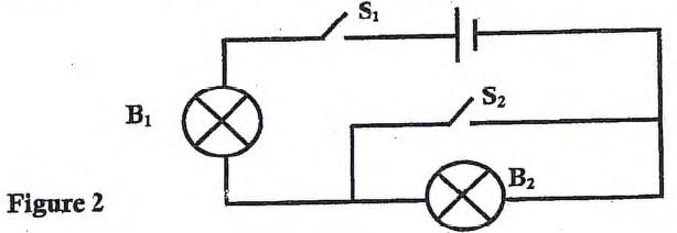
State and explain the observation made on bulbs B1 and B2 when switches S1 and S2 are both closed (2 marks)
Figure 3 shows an X - ray tube used to produce X - rays. Use it to answer questions 4 and 5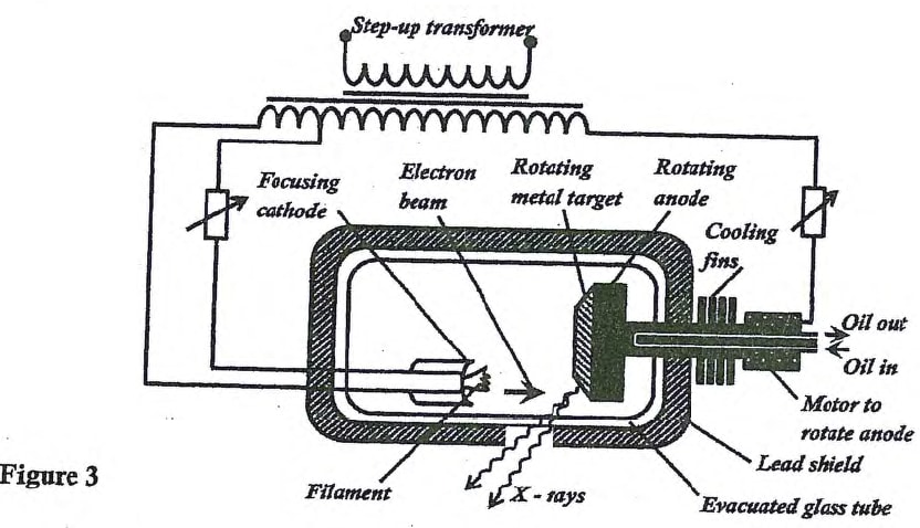
- Give a reason why;
- The metal target is made to rotate (1 mark)
- Lead metal is used to shield the X-ray tube (1 mark)
- The X-ray tube in Figure 3 produces elctrons which are accelerated by a p.d of 12 kV. Assuming all the enrgy goes to produce X- rays, determine the maximum frequency of the X-rays produced. (Planck's constant h= 6.62 × 10⁻³⁴ Js) and charge on an electron, e = 1.6 × 10⁻¹⁹ C) (3 marks)
- Figure 4(not drawn to scale) shows a bright electric bulb placed behind a screen which has a hole with an object cross-wire. A concave mirror of focal length 30 cm is placed in front of the screen. The position of the mirror is adjusted until a sharp image of the cross-wire is formed on the screen
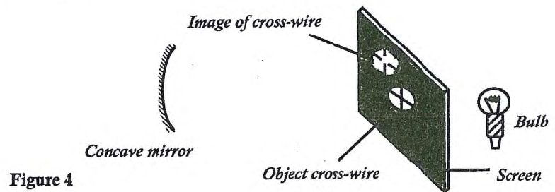
Detrmine the distance between the mirror and the screen (1 mark) - In a house, there is a cooker rated 6 kW. The mains potential is 240 V and the fuses available are 35A, 30 A, 15 A and 13 A. Determine the fuse that would be suitable for the cooker (3 marks)
- When X- rays are passed above the cap of a positively charged electroscope it is observed that the leaf divergence decreases. Explain this observation (2 marks)
- Several 200 Ω carbon resistors are to be connected in a circuit so that a current of 2A flows from a 50 V source. Determine how many resistors are required. (3 marks)
- Figure 5 shows part of a wiring circuit for a house
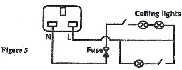
Correct two faults made in the wiring (2 marks) - The current of elctrons hitting the screen of a C.R.O is 15 mA. Given that the charge of one elctron is 1.6 × 10 -19 C, determine the number of electrons that hit the screen per second (2 marks)
- Figure 6 shows an electromagnetic spectrum in the increasing order of wavelength from X to Y
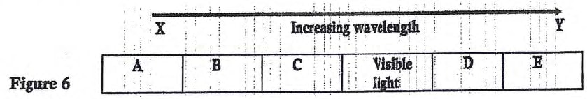
- Identify the region of the spectrum labeled C (1 mark)
- Give one similarity between the spectrum labeled B and the visible light (1 mark)
- Give a reason why electrical power is transmitted over long distances at high voltage (1 mark)
SECTION B (55 Marks)
Answer all the questions in this section
-
- State what is meant by thermionic emission (1 mark)
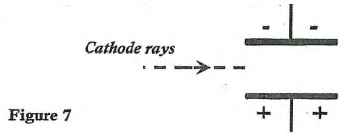
- Figure 7 shows a beam of cathode rays entering the space between two charged metal plates. Continue the dotted line to show the path of the cathode rays as they travel between the plates and into the space beyond the plates (1 mark)
- Figure 8 shows a cathode ray tube of cathode ray oscilloscope (C.R.O)
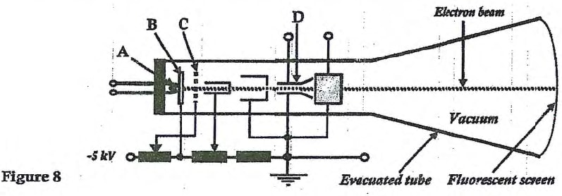
- Name the parts labeled A and D (2 marks)
- What property does the part labeled B have for its efficient functioning (1 mark)
- State the function of the part labeled C (1 mark)
- The figure below shows the trace on the screen of an ac signal connected to the Y plates of a CRO with time base on
Given that the time base control is 50 ms/div, determine the frequency of the a.c signal (3 marks)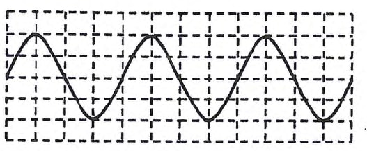
-
- A piece of light object (cork floats on the surface of water as shown in Figure 9 below. A straight edge vibrator placed at point A of the ripple tank generates water waves which travel towards point B
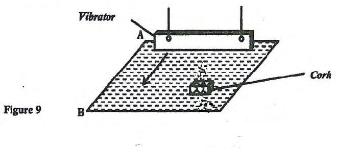
- Successive waves pass the cork every 0.4 secodns and the speed of the wave is 0.5 m/s. Determine the wavelength of the waves (2 marks)
- Indicate on the diagram the direction in which the card moves as the waves pass on it (1 mark)
- Figure 10 shows a ray of light travelling from water towards its interface with air. The critical angle, C of water is 49o
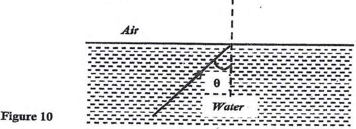
- Skecth the path of the ray on the diagram above after striking the interface at
- An angle if incidence, θ = C. Label the ray as R1 (1 mark)
- An angle of incidence θ >C. Label the ray as R2 (1 mark)
- Calculate the absolute refractive index, n, of water (3 marks)
- Skecth the path of the ray on the diagram above after striking the interface at
- A student struck the prongs of a tuning fork agaisnt a hard surface in the laboratory. The prongs vibrate producing a longitudinal wave passing through air as shown in the Figure 11
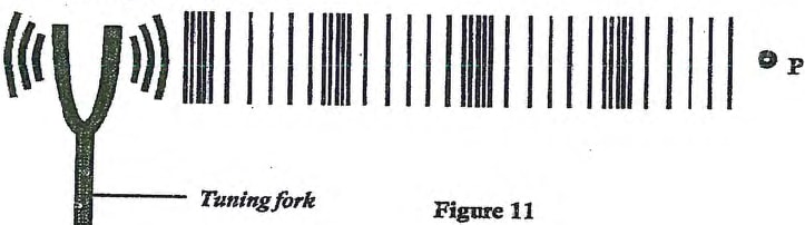
- Label the compression and rarefaction regions in the longitudional wave. (1 mark)
- Using a lline with a double arrow, indicate on the diagram a distance d equal to one wavelength of the wave (1 mark)
- On the diagram, show with an arrow the direction of motion of the air particle P as the waves pass (1 mark)
- State one advantage of optical fibre cable over conventional copper cables as used in telecommunication (1 mark)
- A piece of light object (cork floats on the surface of water as shown in Figure 9 below. A straight edge vibrator placed at point A of the ripple tank generates water waves which travel towards point B
-
- Figure 12 shows ammeters and resistors connected to a battery of em.f. 15.0 V and negligible internal resistance
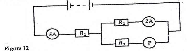
- Find the reading of the meter P
- If the resistance R1 is 1.2 Ω , determine as shown in figure 1 the values of R2
- Figure 13 shows two charged plates P and Q one is earthed and the other is connected using a copper wire to the cap of an elctroscope which was initially unchanged.
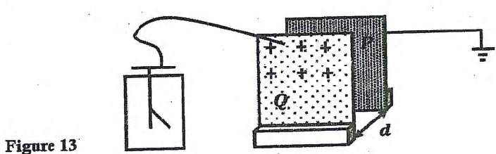
State what happens to the leaf of the eletrocope when plate P is moved sideways while keeping plate Q and distance of separation constant. (1 mark) - Figure 14 shows a circuit where a battery of emf 4.5 V, switches A and B, two capacitors C1 = 0.4 μF and C2 = 0.6 μF and a voltmeter are connected.
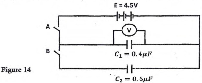
Determine the voltmeter reading when- Switch A is closed and switch B is open (1 mark)
- Switch A is closed and opened, and then B is closed (3 marks)
- Figure 15 shows a conductor C placed on a negatively charged polythene rod. Identify the charges on conducto C and sphere S when C is connected to S using a wire
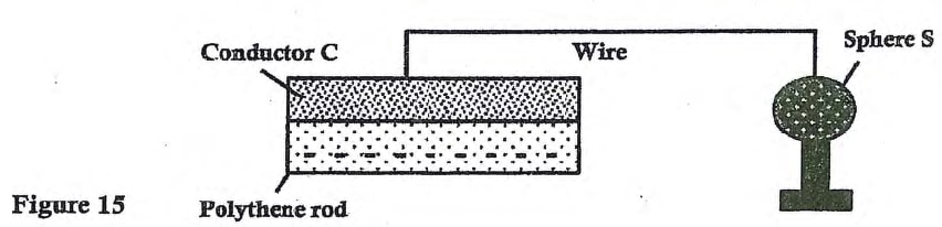
Conductor C (1 mark)
Sphere S (1 mark)
- Figure 12 shows ammeters and resistors connected to a battery of em.f. 15.0 V and negligible internal resistance
-
- Figure 16 below shows a steel bolt being magnetized
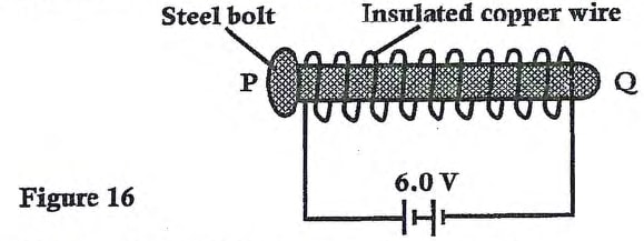
Identify the pole P and Q of the resulting magnet - Figure 17 shows an electric device running on a battery
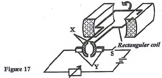
- Name the parts labelled X and Y (2 marks)
- Given the direction of rotation of the coil is as shown in the diragram, indicate the poles of the magnet on the diagram
- If the battery was replaced with a copper wire, sketch on the axes below a graph of induced current against time flowing through the variable resitors if the coil is made to rotate as it is in the figure above (1 mark)
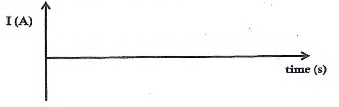
- Suggest an improvement that can be made to increase the magbitude of induced current in (iii) above
- The input voltage of a transformer is 220 V and its output voltage is 12 V. When a 60 W bulb is connectd across the secondary coil, the current in the primary coil is 0.32 A. Determine the efficiency of the transformer (3 marks)
- One of the causes of energy loss in a tranformer is through fromation of eddy currents. State one way in which eddy currents lead to energy loss in a transformer (1 mark)
- Figure 18 shows a connection to a three pin plug
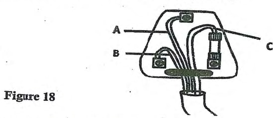
- Identify the leads labelled B and C (2 marks)
- Give a reason why the pin onto which lead A is connected is normlly longer than the other two pins (1 mark)
- Figure 16 below shows a steel bolt being magnetized
-
- Figure 19 shows a human eye with a defect
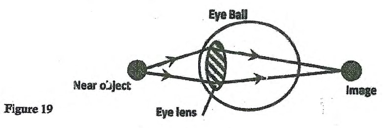
- Name the defect (1 mark)
- State one possible cause of this defect (1 mark)
- A lens forms an image that is four times the size of the object on a screen. If the distance between the object and the screen is 150 cm, determine;
- State with reasons what type of lens was used (2 marks)
- The focal length of the lens (3 marks)
- A barber holds a concave mirror a short distance from his client's face. Given that the described arrangement is as shown on Figure 20 and the radius of curvature is 40 cm
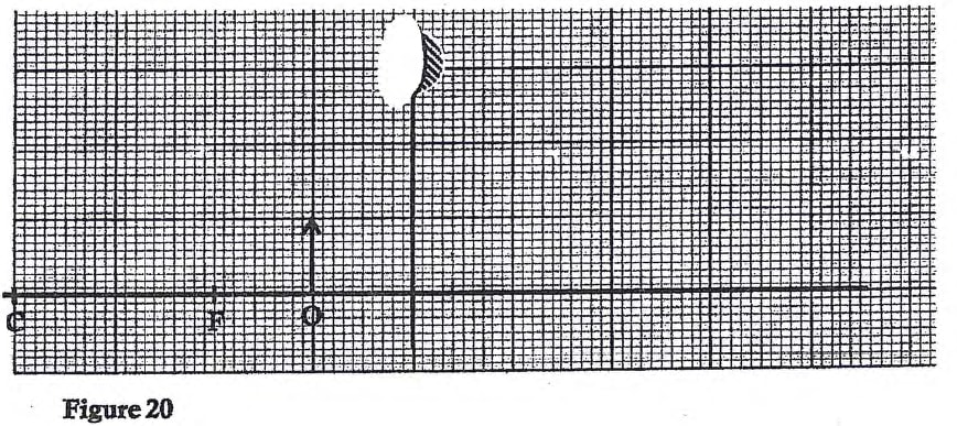
- draw on the same figure, a ray diagram to show the position of the image of the client's face (2 mark)
- Use the ray diagram to determine the magnification of the image (1 mark)
- Figure 19 shows a human eye with a defect
Join our whatsapp group for latest updates
Tap Here to Download for 50/-
Get on WhatsApp for 50/-
Download PHYSICS PAPER 2 - 2019 KCSE Prediction Questions Set 1.
Tap Here to Download for 50/-
Get on WhatsApp for 50/-
Why download?
- ✔ To read offline at any time.
- ✔ To Print at your convenience
- ✔ Share Easily with Friends / Students