
EXERCISE 1
Using the components, materials and equipment provided, carry out the following tasks
- Connect the circuit as shown in Figure 1. Let the examiner check your work (7 marks)
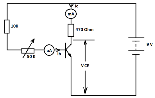
- Figure 1
- Vary the base resistance RB to obtain each of the base current IB values shown in table 1. For each value of IB, measure and record in the table the corresponding values of VCE and IC.
Table 1
IB(µA)
VCE(V)
IC(mA)
200
220
240
260
280
300
- Determine the current gain β when IB=240µA (2 marks)
- Plot a graph of IC against VCE (5 marks)Using the values in table 1:
EXERCISE 2
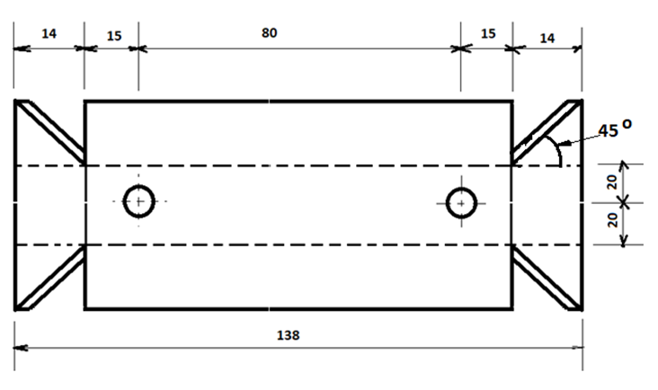
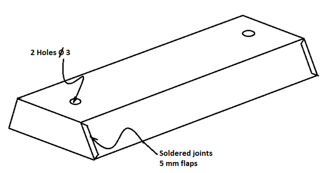
Using the tools and equipment provided, make the model of a fluorescent lamp rain guard as shown in Figure 2
EXERCISE 3
Using the components, materials and equipment provided, perform the following tasks.
- Connect the circuit shown in Figure 3 and let the examiner check your work (6 marks)
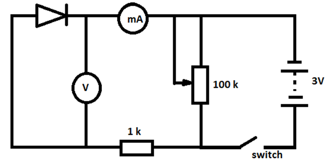
- Close the switch. Adjust the potentiometer to obtain voltage reading shown in Table 2. For each voltage reading obtained, measure and record the corresponding current values. (5 marks)
Table 2
Voltage (V)
0
0.5
0.7
0.9
1.3
1.7
Current (mA)
Plot a graph of current against voltage (6 marks)
- From the graph:
- Determine the resistance when the voltage is 1.3V
- Give a reason for the shape of the graph (3 marks)
EXERCISE 4
Using the pre-fabricated circuit provided in Figure 4, perform the following tasks: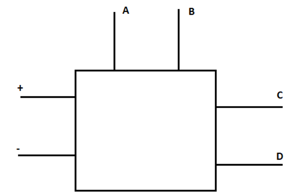
- With the switch open:
- Connect Voltmeter between A and B (Observe polarity)
- Connect Voltmeter between C and D (Observe polarity) (2 marks)
(Let the examiner check your work)
- Close the switch. Adjust input voltage and complete the table below (10 marks)
Table 3
Input Voltage Vin (V)
0
1.0
2.0
3.0
4.0
5.0
6.0
7.0
8.0
9.0
10.0
Output voltage Vz (V)
Plot the graph of Vz against Vin (5 marks)
EXERCISE 5
Using PVC sheathed wiring, complete the installation shown in Figure 5, such that the bell is operated from either A or B (20 marks)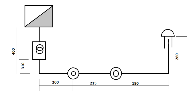

MARKING SCHEME
EXERCISE 1
|
|
AREA TO BE MARKED |
MAXIMUM SCORE |
ACTUAL SCORE |
|
1 |
10KΩ |
1 |
|
|
2 |
Potentiometer |
1 |
|
|
3 |
470Ω |
1 |
|
|
4 |
BJT |
1 |
|
|
5 |
mA |
1 |
|
|
6 |
µa |
1 |
|
|
7 |
Vcc |
1 |
|
|
TOTAL MARK |
7 |
EXERCISE 2
|
|
AREA TO BE MARKED |
MAXIMUM SCORE |
ACTUAL SCORE |
|
1 |
Dimensions 15,15,15,15 |
2 |
|
|
2 |
Cutting 4x1 |
4 |
|
|
3 |
Hole location 4x ½ |
2 |
|
|
4 |
Hole drilling 2x1 |
2 |
|
|
5 |
Folding 8x ½ |
4 |
|
|
6 |
Angle 45o 2x1 |
2 |
|
|
7 |
Deburring |
1 |
|
|
8 |
Soldering |
2 |
|
|
9 |
Appearance |
1 |
|
|
TOTAL |
20 |
EXERCISE 3
|
|
AREA TO BE MARKED |
MAXIMUM SCORE |
ACTUAL SCORE |
|
Diode |
1 |
||
|
Resistor |
½ |
||
|
Potentiometer |
1 |
||
|
Power source |
1 |
||
|
Voltmeter |
1 |
||
|
Milliameter |
1 |
||
|
Switch |
½ |
||
|
SUB-TOTAL |
6 |
EXERCISE 4
|
AREA TO BE MARKED |
MAXIMUM SCORE |
ACTUAL SCORE |
|
|
1 |
Voltmeter (Vin) |
1 |
|
|
2 |
Voltmeter (Vz) |
1 |
|
|
3 |
Source |
1 |
|
|
Sub total |
2 marks |
EXERCISE 5
|
AREA TO BE MARKED |
|
MAXIMUM SCORE |
ACTUAL SCORE |
|
|
1 |
Dimensions (±2mm) |
5x ½ |
2 ½ |
|
|
2 |
Fixing components firm and level |
(3x1) |
3 |
|
|
3 |
Correct choice of cables |
(2x ½ ) |
1 |
|
|
4 |
Cable runs (flat on surface) -horizontal -Vertical -Cable bends |
3x ½ 3x ½ 2x ½ |
1 ½ 1 ½ 1 |
|
|
5 |
Uniform spacing of staples and buckle clips |
1 |
||
|
6 |
Cable terminations (Twisted, folded, firm and not Nicked) at: -push buttons -Bell transformer -Bell -CCU |
1x2 1x1 1x1 1x1 |
2 1 1 1 |
|
|
7 |
Correct circuit connection -push button A and B controls bell |
(2x1) |
2 |
|
|
8 |
Earthing of transformer |
1 |
||
|
9 |
Colour code |
½ |
||
|
TOTAL |
20 |
Download ELECTRICITY PAPER 2 - 2019 LAINAKU JOINT MOCK EVALUATION EXAMINATION.
Tap Here to Download for 50/-
Get on WhatsApp for 50/-
Why download?
- ✔ To read offline at any time.
- ✔ To Print at your convenience
- ✔ Share Easily with Friends / Students