
ELECTRICITY
PAPER 2
INSTRUCTIONS TO CANDIDATES
- Candidates should have the following for this examination
- Answer booklet
- Drawing instruments
- Mathematical tables
- Drawing paper size A3
- Answer ALL the questions
- All dimensions are in millimeters unless otherwise stated.
- Each question takes 30 mins
Exercise 1
- using the components, materials and equipment provided, carryout the following tasks
- Connect the circuit as shown in the figure below. Let the examiner check your work.

- Vary the base resistance RB to obtain each of the base current IB values shown in table 1. For each value of IB , measure and record in the table the corresponding values of VCE and Ic
IB (µA) VCE (V) Ic (mA) 200 220 240 260 280 300 - Using the values in table 1:
- Determine the current gain β when IB =240µA 2mks
- Plot a graph of Ic against VCE. 5mks
- Connect the circuit as shown in the figure below. Let the examiner check your work.
Exercise 2
- Use tools and materials to fabricate the candle holder shown below.

Exercise 3
- Use the tools, equipment and materials provided to carry out the following task; a) terminate the three core flexible cable to the top plug and the iron box 15mks.
- Turn on the thermostat switch to ON position, measure and record the values of resistance between;
- Live and neutral at plug………………………………………
- Live and earth at plug…………………………………………
- Earth at plug and iron box body………………………………
- Neutral at plug and at the iron box……………………………5mks.
Exercise 4.
Using components and equipment provided perform the following task. Let the examiner check your work.
- On the breadboard, connect the circuit components as shown below. 3mks
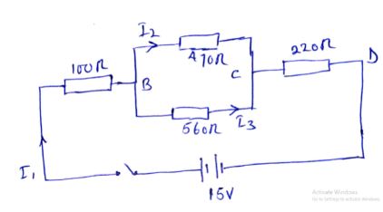
- Connect the circuit and measure the voltage and current across and through 470Ω resistor. V………………………………..I……………………..2mks
- Measure and record the values of current and voltage across the 220Ω resistor.
V………………………………………….I…………………………..2mks - Measure and record the values of voltage and current
- 100Ω load resistor
V=………………………………..I=…………………………2mks - 560Ω load resistor
V=………………………………..I=,…………………………..2mks
- 100Ω load resistor
- Calculate the values in ii,iii and iv above and compare them wit the measured value. State the difference obtained. Account for the difference 9mks
Exercise 5
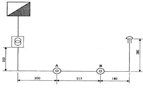
- Using PVC sheathed wiring, complete the installation shown below. Such that the bell is operated from either A or B. 20mks.
CONFIDENTIAL
EXERCISE 1
- variable power supply ( 0-30v)
- Ten 470 ohms carbon resistors
- Ten 10K carbon resistors
- Ten 47k variable resistors
- Ten BC 101 NPN resistors
- Enough Connecting wires
- Enough Jumper wires
- five milli-ammmeters (0-100mA)
- five micro-ammeters 0-500µA
- bread board
EXERCISE 2
- tin snips
- scriber
- drilling machine
- bench vice
- mallet
- steel nail
- soldering gun
- solder wire
EXERCISE 3
- iron box (in good condition)
- multimeters
- tester
- screw driver
EXERCISE 4
- ten 100 ohms resistors
- ten 470 ohms resistors
- ten 560 ohms resistors
- ten 220 ohms resistors
- power supply
- enough connecting wires
- enough jumper wires
- bread board
- voltmeters (0-999v)
- ammeters (0-100mA)
EXERCISE 5
- consumer control unit
- ransformer 240v/12v
- two push buttons
- 12v bell
- 1.5mm2 cable twin with earth
- Electrician tool box
- Two Shallow patresses
MARKING SCHEME
EXERCISE 1
| Areas to be marked | Maximum Score | Candidate score |
| Correct connection | 3 | |
| Sub Total | 3 |
EXERCISE 2
| Areas to be marked | Maximum Score | Candidates Score |
| Correct dimension 8 × ½ | 4 | |
| Holes location – correct location | 2 | |
| Drilling | 2 ½ | |
| Cutting 8 × ½ | 4 | |
| Folding 3 × ½ | 1½ | |
| Flaps formation 2×1 | 2 | |
| Soldering 2 × 1 | 2 | |
| Finishing 2 × 1 | 2 | |
| SUB TOTAL | 20 |
EXERCISE 3
| Areas to be marked | Maximum Score | Candidate Score |
| Total marks | 20 |
EXERCISE 4.
| Areas to be marked | Maximum Score | Candidate Score |
| Correct connection 6× 1/2 | 3 | |
| Subtotal | 3 |
EXERCISE 5
| Areas to be marked | Maximum score | Candidate score |
| Dimension 8 × ½ | 4 | |
| Fixing components 5 × ½ | 3 | |
| Vertical cable runs 3 × ½ | 2 | |
| Horizontal run (flat) 2 × ½ | 2 | |
| Uniform spacing of clips | 2 | |
| 90o bend | 1 | |
| Correct circuit connection | ||
| CCU | ||
| BELL | ||
| Bell pushes | 3 | |
| Correct cable termination (firm and not knicked) | ||
| CCU | 1 | |
| Bell | 1 | |
| Bell pushes | 1 | |
| SUB TOTAL | 20 |
Join our whatsapp group for latest updates
Tap Here to Download for 50/-
Get on WhatsApp for 50/-
Download Electricity Paper 2 Questions and Answers - MECS Cluster Joint Pre Mock Exams 2021/2022.
Tap Here to Download for 50/-
Get on WhatsApp for 50/-
Why download?
- ✔ To read offline at any time.
- ✔ To Print at your convenience
- ✔ Share Easily with Friends / Students