
PHYSICS
PAPER 2
FORM 4 MID TERM 2
INSTRUCTIONS
- This Paper has Section A nd B. Answer all questions in Section A nd B
- Working must be clearly shown.
SECTION A(25MKS)
Answer all questions in this section in the spaces provided
- Figure 1 shows a ray of light incident on a mirror at an angle of 45º. Another mirror is placed at an angle of 45º to the first one as shown
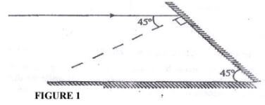
Sketch the path of the ray until it emerges (2 mks) - A positively charged sphere is suspended by an insulating thread. A negatively Charged conductor is suspended near it. The conductor is first attracted, after touching the sphere, it is repelled. Explain this observation. (2mks)
- Figure 2 shows a soft iron bar AB placed in a coil near a freely suspended magnet.
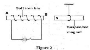
Explain the observation made when the switch is closed. (2 mks) - Table 1 shows radiations and the irrespective frequencies.
Arrange the radiations in the order of increasing energy. (1 mk)Type of radiation Yellow light Gamma rays Radio waves Micro waves Frequency (Hz) 1 x 10¹⁵ 1 x 10²² 1 x 10⁶ 1 x 10¹¹ - A heating coil is rated 100W, 240V. At what rate would it dissipate energy if it is connected to a 220V supply? (3mks)
- Figure 3 shows a ray of light incident on the face of a water prism
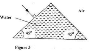
Sketch the path of the ray as it passes through the prism. Critical angle for water is 490 (1 mk) - State the reason why electrical power is transmitted over long distances at very high voltages. (1 mk)
- A boy standing in front of a cliff blows a whistle and hears the echo after 0.5s. He then moves 17 metres further away from the cliff and blows the whistle again. He now hears the echo after 0.6s. Determine the speed of the sound. (3 mks)
- Figure 4 shows a human eye with a certain defect
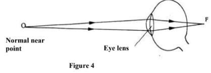
- Name the defect (1 mk)
- On the same diagram, sketch the appropriate lens to correct the defect and sketch rays to show the effect of the lens. (2mks)
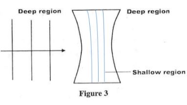
- Figure 5 shows straight waves incident on a diverging lens placed in a ripple tank to reduce its depth.
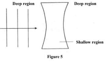
Complete the diagram to show the waves in both the shallow region and beyond the lens (2 mks) - A narrow beam of electrons in a cathode ray oscilloscope (CRO) strike the screen producing a spot. State what is observed on the screen if a low frequency a.c source is connected across the y-input of the CRO (1mk)
- Polarisation is a defect of a simple cell. State how it reduces the current produced and how this defect can be minimized (2 mks)
- The figure 6 below shows a d.c generator.
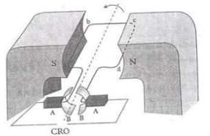
Name the parts labeled A and B (2marks)
SECTION B (55 MKS):
Answer all questions in this section in the spaces provided.
-
- State Ohm’s Law (1 mk)
- The graph in figure 7 shows the current – voltage characteristics of a certain device, X
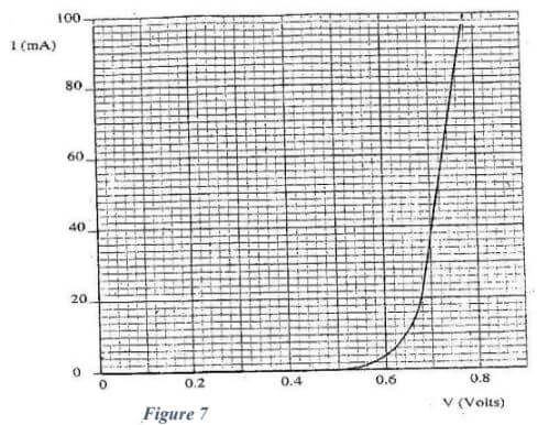
- State with a reason whether the device obeys Ohm’s law (2 mks)
- Determine the resistance of the device, X, when the current through it is 60 mA. (3 mks)
- When the device, X is connected in the circuit below, the voltage across it is 0.70 V.
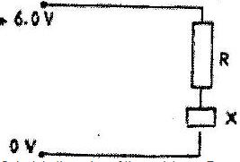
Calculate the value of the resistance R. (3 mks)
- The cell in figure has an e.m.f of 2.1 V and negligible internal resistance.
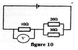
Determine the- Effective resistance in the circuit (2 mks)
- Current in the circuit (1 mk)
- Reading of the voltmeter (2 mks)
-
- The figure below shows the displacement-time graph of a wave traveling at 400cm/s.
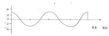
Determine for the wave, the :- Amplitude (1mk)
- Period (1mk)
- Frequency (2mks)
- Wavelength (3mks)
-
- How are sound waves different from radio waves. (1mk)
- Figure 9 below shows the waves starting from two coherent sources S1 and S2.
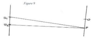
What would be observed at P if the waves are;- Light waves (1mk)
- Sound waves (1mk)
- The figure below shows the displacement-time graph of a wave traveling at 400cm/s.
-
- The Figure, shows a circuit that may be used to charge a capacitor.
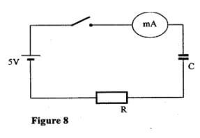
- State the observation on the milliameter when the circuit is switched on: (1mk)
- Explain the observation in (i) above. (2mks)
- The circuit in figure 8 is left on for some time. State the value of p.d. across:
- the resistor R; (1mk)
- the capacitor C; (1mk)
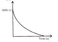
- Sketch the graph of potential difference (V) across R against time. (3mks)
- The Figure shows three capacitors connected to a 10V battery.
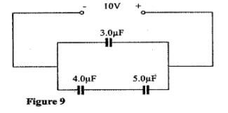
Calculate:- the combined capacitance of the three capacitors; (3mks)
- the charge on the 5.0 μF capacitor. (2mks)
- The Figure, shows a circuit that may be used to charge a capacitor.
-
- Figure 12 shows two circuits close to each other
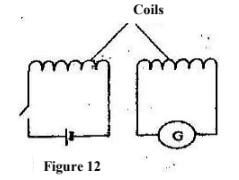
When the switch is closed, the galvanometer shows a reading and then returns to zero. When the switch is then opened, the galvanometer shows a reading in the opposite direction and then returns to zero. Explain these observations. (3 mks) - An ideal transformer has 2000 turns in the primary circuit and 200 turns in the secondary circuit. When the primary circuit is connected to a 400V a.c. source the power delivered to a resistor in the secondary circuit is found to be 800W. Determine the current in:
- The secondary circuit (3 mks)
- The primary circuit (3 mks)
- Explain how energy losses in a transformer are reduced by having a soft- iron core (2 mks)
- Figure 12 shows two circuits close to each other
-
- The graph figure below shows the relationship between 1/u and 1/v for a converging lens where u and v are the object and image distances respectively.
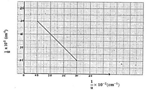
From the graph, determine the focal length, f of the lens. (3 marks) - Figure below shows an experimental set up consisting of a mounted lens, I, A screens, a metre rule and a candle

- Describe how the set up may be used to determine the focal length f, of the lens. (3 marks)
- State why the set up would not work if the lens were replaced with a diverging lens. (1mark)
- The graph figure below shows the relationship between 1/u and 1/v for a converging lens where u and v are the object and image distances respectively.
MARKING SCHEME
-
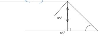
mk for showing all rays
1 mk for angles shown - The conductor is initially attracted because of opposite charge. It is then neutralized and charged positive/negative, hence repelled
- The suspended bar magnet is repelled. The soft iron bar is magnetized and end B becomes the North pole hence like poles repel.
- Radio waves → microwaves → yellow light → gamma rays
- P = V2/R P = 2202
2402
100
R = 2402
100
= 84 J/S 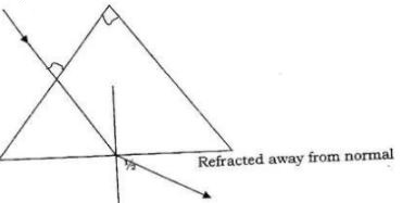
- High voltage leads to low current hence low power losses or energy loss
- 2d/05 = 2d/0.6 + 34 OR V = d/t
D = 17/0.2 = 85 m = 17 x 20.1
Speed = 2 x 86 = 340 m/s
0.5
= 340m/s -
- Long sightedness/ hypermetropia
- corrected using a convex/ converging lens; check rays converged at retina.
-
- Spot moves up and down
- Polarisation reduces current by production of hydrogen bubbles around the negative plate; can be reduced by adding a depolarizer e.g manganese (iv) oxide
- A – Carbon brush (reject brushes)
B - split ring/ commutator -
- The ratio of the pd across the ends of a metal conductor to the current passing through it is a constant (conditions must be given)
-
- It does not obey Ohm’s law; because the current – voltage graph is not linear through line origin / directly proportionate
- Resistance = V/l = inverse of slope; gradient = ∆ l/∆V
= (0.74 – 0.70) V
(80 – 50) mA
= 0.4V
30 x 10-3 A
= 1.33Ω
1.20 – 1.45 Ω (range) ( 3 mks) - From the graph current flowing when pd is 0.70 is 60.MA
Pd across R = 6.0 – 0.7 = 5.3v
R = 5.3 V
36mA
= 147Ω
= 139.5 – 151. 4Ω ( 3 mks)
-
- Parallel circuit 1/30 + 1/20 = 5/60 or 60/50
R = 12 Ω
Total resistance = 10 + 12 = 22Ω ( 2 mks) - l = V/R =2.1/22 = 0.095A ( 1 mk)]
- V = lR = 10 x 2.1/22
= 0.95 V
- Parallel circuit 1/30 + 1/20 = 5/60 or 60/50
-
-
- 3cm;
- T = 0.8/2
= 0.4seconds; - f = 1 /T;
=1/0.4
= 2.5Hz; - V = fλ;
λ=V/f
= 4/2.5 ;
= 1.6m/s ;
-
- sound waves are longitudinal in nature while radio waves are transverse in nature.
- bright fringes are observed
- louder sound is heard
-
-
-
- Current falls off to zero / falling to zero / deflects to max. Then zero
- Reducing gradually or after sometime.
- Current flows when the capacitor is charging
- When fully charged current stops (no current) and p.d is equal to charging voltage
- VR = 0 V
VC = 5V -
-
- 1/c5=1/4+1/5=5+4/20=9/20
Cs=20/9
c1=20/9 + 3=5.22μF
Accept 5.22μF only - Change of series section=Q=Cv
=20/9x10x1μF
=22.2μC
Q series=Qt-Q3μF
=(5.22-3)x10μC
=22.2μC
- 1/c5=1/4+1/5=5+4/20=9/20
-
-
- Flux growing/ linking
No flux change
Flux collapsing
Switch closed: Flux in the coil grows and links the other coil inducing an
E.M.F
Current steady: No flux change hence induced E.M.F
Switch opened: Flux collapses in the R.H.S coil inducing current in opposite direction -
- VP = NP P = IsVs
Vs Ns Is = 800/40
400 = 200
Vs 200
Vs = 40 Volts = 20A - Pp Ps
800 = 400 Ip
Ip = 800/400
= 2A
- VP = NP P = IsVs
-
- Reduces losses due to hysteresis (or magnetic losses)
- Because the domain in soft- iron respond quickly to change in magnetic (or have
- low reluctance) i.e easily magnetized and demagnetized.
- Flux growing/ linking
-
- At 1/u intercept, 1/v = 2.5 ×10⁻² cm-1
1/f =1/u + 1/v
= 2.5 ×10⁻²
∴ f = 1/2.5 × 10-2 11/0.025 = 40cm -
-
- Adjust the position of the lens until a sharp image of the flame is observed1
- Record the object distance (u) and the image distance (V)
- Repeat with different object positions1
- Use the relation f = uv/u+v to determine f
- Diverging lens produces a virtual image which cannot be formed on a screen
-
- At 1/u intercept, 1/v = 2.5 ×10⁻² cm-1
Join our whatsapp group for latest updates
Tap Here to Download for 50/-
Get on WhatsApp for 50/-
Download Physics Paper 2 Questions and Answers - Form 4 Mid Term 2 Exams 2021.
Tap Here to Download for 50/-
Get on WhatsApp for 50/-
Why download?
- ✔ To read offline at any time.
- ✔ To Print at your convenience
- ✔ Share Easily with Friends / Students