
SECTION A (44 marks)
Answer all questions in this section in the spaces provided.
- Outline the following:
- Four safety precautions when using electrical equipment. (2 marks)
- Two safety precautions when working on aircraft electrical system. (1 mark)
-
- State the use of each of the following types of rivets used in aircraft construction:
- Countersunk head rivet,
- Mushroom head rivet. (2 marks)
- Explain why aluminium alloy is preferred for use in aircraft construction (1 mark)
- State the use of each of the following types of rivets used in aircraft construction:
-
- Highlight two functions for each of the following aircraft structural members:
- Frame,
- Stringer,
- Skin.
(3 marks)
- Differentiate between eddy current and ultra-sonic methods of non destructive testing, (2 marks)
- Highlight two functions for each of the following aircraft structural members:
- Distinguish between the following as applied in airport operations:
- Flight plan and forecast, (2 marks)
- Flight and ground visibility. (2 marks)
- Using sketches, explain the operation of each of the following pneumatic system valves:
- Non-return, (2½ marks)
- Orifice. (2½marks)
-
- Name four joining methods used in aircraft construction. (2 marks)
- State two advantages for each method in (a). (4 marks)
- With the aid of a sketch, describe the three aircraft axes. (5 marks)
- Explain the operation of each of the following jet engine components:
- Compressor, (2 marks)
- Turbine, (2 marks)
- Exhaust. (2 marks)
- Highlight the information given to the aircrew by the air traffic controller. (3 marks)
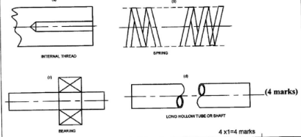
- Sketch the symbols for each of the following:
- Internal thread, (1 mark)
- Bearing, (1 mark)
- Spring, (1 mark)
- Long hollow tube or shaft. (1 mark)
SECTION B (56 marks)
Answer any four questions from this section in the spaces provided
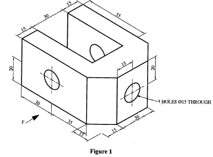
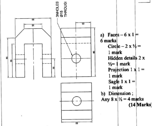
- Figure 1 shows an aircraft locking bracket drawn in isometric projection.
- Draw Full Size the following views in third angle projection:
- Front elevation in the direction of arrow F.
- End elevation,
- Plan (10 marks)
- Show the major dimensions. (4 marks)
- Draw Full Size the following views in third angle projection:
-
- With aid of a labelled sketch describe the three aircraft propeller blade angles during flight. (10 marks)
- Describe the four forces which act on a propeller during flight. (4 marks)
-
- With aid of a labelled schematic diagram, explain the functions of each component of a basic hydraulic system.
(12 marks) - State four functions of a hydraulic system accumulator. (2 marks)
- With aid of a labelled schematic diagram, explain the functions of each component of a basic hydraulic system.
-
- Explain the importance and location of each of the following aircraft crash and rescue equipment:
- Escape slide,
- Dinghy,
- Life jacket,
- Life raft. (8 marks)
- With the aid of sketches, show the difference between static and dynamic stability. (6 marks)
- Explain the importance and location of each of the following aircraft crash and rescue equipment:
-
- Define each of the following terms as applied in aircraft instrument system:
- Dynamic pressure,
- Static pressure. (2 marks)
- With the aid of a labelled diagram describe a tropical magneto primary circuit used on aeroniston engine.
- Define each of the following terms as applied in aircraft instrument system:

MARKING SCHEME
-
- Safety precautions observed while working with electrically operated tools/equipment.
- Electrical cables should not be allowed to run over sharp edges, through oil, fuel or water on the ground.
- Never work with electrically operated equipment with wet hands or feet in wet or damp areas.
- Never use electrical equipment in hazardous areas such as fuel tanks unless the equipment is specially designed for the job as is approved.
- Ensure all equipment are earthed via a suitable plug or be of the double insulated type.
- Ensure that cables are secure, undamaged and the correct fuse is fitted.
- Ensure the equipment has a serviceable label fitted.
Any 4x½=2 Marks
- Safety precautions while working on aircraft electrical system.
- Ensure all unnecessary equipment are switched off
- Ensure fuse/CB are pulled out and tag on any circuit that is to be worked on
2x½(1 mark)
- Safety precautions observed while working with electrically operated tools/equipment.
-
-
- Countersunk head rivet - used on aircraft surfaces subjected to airflow in order to reduce drag (flush with the surface)
- Mushroom head rivet - used on aircraft surfaces not subjected to airflow (especially interior surfaces and aircraft skin)
2x1= (2 markb
- Aluminum alloy is preferred the most suitable material for aircraft construction due to its;
- Strength
- Light weight
2x½(1 mark)
-
-
- Function of semi monocoque structural members
- Frames
- They strengthen the fuselage and spread the load. Also provide an oval and aerodynamic shape.
- Reduces the column length of the stringers to prevent instability. i
- Stringers
- They support and reinforce the skin.
- Provide attachement to the skin.
- Gives shape to the wing
- Skin
- provide smooth flow of air and give shape to the fuselage.
- Keeps the fuselage rigid
3x1= (3marks)
- Frames
- Solution
- Eddy current
An electric current is subjected to a specimen and the frequency observed. A flow is indicated either by audio peeping sound or on an Oscilloscope. - Ultrasonic
A sound wave is transmitted to the specimen and the reflection frequency is observed on a screen. The longer wave indicates no fault. (A shorter reflection indicates a crack). I.e. The method uses a transmitter and a receiver.
2x1= 2 marks)
- Eddy current
- Function of semi monocoque structural members
-
- Definitions
- Flight plan
Specified information provided to Air Traffic services Unit related to an intended flight or portion of a flight of an aircraft. - Forecast
A statement of expected meteorological condition for specified time or period, and for specified area or portion of airspace.
- Flight plan
-
- Flight visibility
The visibility forward from the cockpit of an aircraft in flight. - Ground visibility
The visibility at an aerodrome as reported by an accredited observer.
4x1=4 marks)
- Flight visibility
- Definitions
-
- Description of Pneumatic components
Non-return valve (check valve)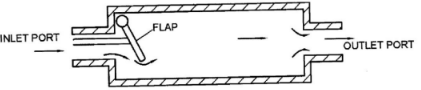
In pneumatic a flap type non-return valve, air enters an outlet port of the non-retum and compresses a light spring, forcing the non-return valve open and allowing air to flow out an outlet port. However if air enters pressure closes the valve preventing a back flow of air,
Sketch 1x1=1
Explanation 1 x 1½ mark) =1½ - Orifice Restrictor
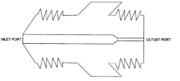
The orifice restrictor has a large inlet port and a small outlet port. The small outlet port reduces the rate of airflow and the speed of operation of an activating unit.
Sketch 1 x1 = 1
Explanation 1 x 1½ marks = 1½
2½marks
- Description of Pneumatic components
-
- Solution
- Riveting
- Welding
- Bonding (adhesive)
- Soldering
4x½= (2 marks)
-
- High strength and light joints semi-permanent
- Strong and permanent joints
- Light and smooth surface finish.
- Good conductivity and low heat application.
4x1= (4 marks)
- Solution
-
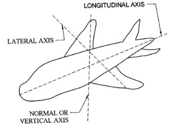
- Longitudinal axis
A line that passes through the nose of the aircraft and exits through the tail. - Lateral axis
A line that passes through the wing tip of one wing and exits through the other wing tip. - Normal axis
A line that passes through the underside of the fuselage and exits through the top.
Sketch 2
Description 3 x 1
5 marks
- Longitudinal axis
-
- Compressor
The compressor converts mechanical energy from the turbine into kinetic energy in the air. The compressor accelerates the air which then flows through a diffused slowing it down and converging most of the kinetic energy into potential energy and some into heat. - Turbine
The turbine is the power producing component in a gas turbine engine. About % of the energy in the gases leaving the combustion section is converted into shaft hosepower and is used to drive the compressor and fan. The remaining energy drives the accessories and accelerated the gases to produce thrust. - Exhaust
After the gases leave the turbine the flow through a duct formed between the exhaust cone and the exhaust or tail pipe. Depending on the aircraft design the exhaust can be divergent or convergent - divergent.
3 x 2= (6 marks)
- Compressor
- Solution
- Changes in meteorological conditions
- Changes in visibility condition
- Essential traffic
3x1= 3marks)
-
-
-
-
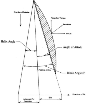
- Blade Angle (Pitch)
the propeller blade is set into its hub so that its chord line forms an angle with the plane of rotation of the Whole Propeller. - Angle of Attack.
This is the angle between relative air flow path and chord line. - Helix angle ( angle of advance)
The angle formed between the relative airflow and plane of rotation
Labelling any (8x½mark) = 4 marks
Sketch (3x1) = 3 marks
Description (3x1) = 3 marks
- Blade Angle (Pitch)
- Four forces which act on a propeller during flight.
- Centrifugal force
This is a force which induce radial stress in the blade and hub, and when acting on material which is not on the blade axis, also induce a twisting moment. - Thrust forces
These are forces which tend to bend the blades forward in the direction of flight. - Torque forces
These are forces which tend to bend the blades against the direction of rotation. - Airloads (Aerodynamic)
These forces normally tend to oppose the centrifugal twisting moment and coarsen blade pitch.
4x1= 4marks
- Centrifugal force
-
-
- Basic hydraulic system
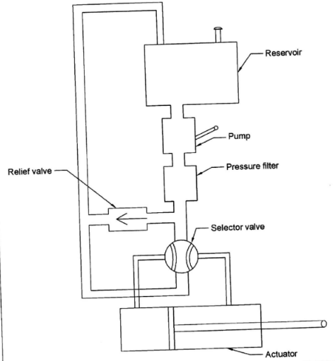
- Reservoir
- Stores the system hydraulic fluid
- Delivers fluid to the pump and receives fluid from the activator.
- Pump
- Delivers fluid under pressure to the system.
- Pressure Filter
- Ensures the fluid is clean by removing all types of dirt.
- Selector Valve
- Selects the direction of the flow of the fluid to the required service and provide a return path for the fluid to the reservoir.
- Activator
- To move the component or surface to the desired direction
(Convert fluid energy to mechanical energy)
- To move the component or surface to the desired direction
- Relief Valve
- Acts as a safety device by relieving the excess pressure from the system.
Sketch=3 3 marks
Labelling =6x ½ 3 marks
Functions = 6 6marks
- Acts as a safety device by relieving the excess pressure from the system.
- Reservoir
-
- Stores hydraulic pressure for emergency
- Caters for pump fluctuations
- Provides pressure incase of leakage.
- Cushions the system operation.
(4 x ½marks) (2 marks)
- Basic hydraulic system
-
- Function and location of the following aircraft crash and rescue equipment.
- Escape slide
Used for the emergency evacuation of the crew and passengers during aircraft crash/ditching. They are located at the bottom inner face of entrance and service doors of the aircraft. - Dinghy
Used to provide floatation of the crew and passengers during aircraft crash/ditching in sea.
Located inside the aircraft crew compartment and also at the entrance/ service doors of the aircraft. - Life Jacket
Used as a personal floatation equipment and located underneath each crew/passenger's seat. - Life raft
Used to provide floatation of crew/passengers but carriers small numbers than the dinghy. They are located on the emergency exits of the aircraft.
4 x 2 = 8 marks
- Escape slide
-
- Static
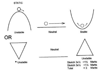 3 Marks
 -
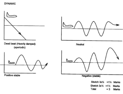 3 marks
- Static
- Function and location of the following aircraft crash and rescue equipment.
-
- Solution
- Dynamic pressure - This is the pitot pressure generated by the aircrafts movement thorugh the atmosphere.
- Static pressure - This is the still (ambient) pressure surrounding the aircraft.
2x1=2 marks
- Solution
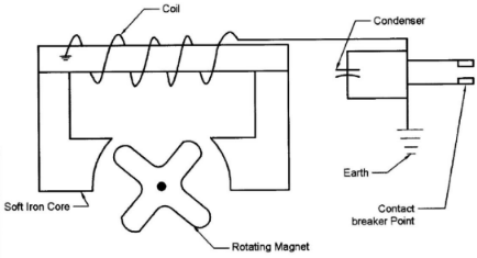
The primary clectricity circuit consists of:- Contact breaker points
- Condenser (capacitor)
- The condenser is wired in parallel with the breaker points. It prevents arcing.
- An insulated coil made up of a few turns of heavy copper wire.
- One end of coil is grounded to the coil core.
- The other end is grounded at the breaker point.
- The circuit is complete when the U-grounded breaker point contacts the grounded breaker point.
Labelling 6 x½ = 3 marks
Sketching 3 x 1 = 3 marks
Description any 6x1 = 6 marks
(12 marks)
- Solution
Join our whatsapp group for latest updates
Tap Here to Download for 50/-
Get on WhatsApp for 50/-
Download KCSE 2017 Aviation Paper 1 with Marking scheme.
Tap Here to Download for 50/-
Get on WhatsApp for 50/-
Why download?
- ✔ To read offline at any time.
- ✔ To Print at your convenience
- ✔ Share Easily with Friends / Students