
Instructions to candidates:
- This paper consists of TWO Sections: A and B.
- Answer ALL the questions in section A and B in the spaces provided.
- All working MUST be clearly shown.
- KNEC mathematical tables and silent non-programmable electronic calculators may be used.
- Candidates should answer the questions in English.
SECTION A (25 MARKS)
Answer All the questions in this section in the spaces provided
- Figure 1 shows the path of a ray of light after striking two mirrors at an angle. Determine the angle between the two mirrors. (Show your working) (1 mark)
 Figure 1
 - Polarization is a defect of a primary cell.
- Define polarization (1 mark)
- State the other defect. (1 [mark)
- Determine the time it will take a ray of light to traverse a transparent glass block of length 20cm given that the velocity of light in air is 3.0 × 10⁸ms−1. (Take the absolute refractive index of glass as 1.5)
(3 marks) - State one other factor that increases the speed of sound in solid a part from increase in temperature.
(1 mark) - Figure 2 shows an object placed at the center of curvature of a concave mirror. Draw a ray diagram to show how the image of the object is formed by the mirror. (2 marks)
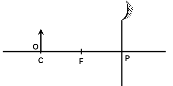
Figure 2 - A charge of 240μC flows through a conductor of resistance 4kΩ in 2 minutes . Determine the work done to move the charge through the conductor. (3 marks)
- State the reason why radio signals have clear reception than television signals in area that is surrounded by hills. (1 mark)
- physics student dipped a bar magnet into iron fillings during an experiment in the lab. When the student lifted the bar magnet, the distribution of iron fillings around the bar magnet was as shown in Figure 4.
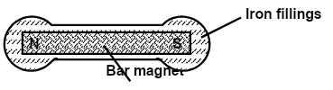
Figure 4
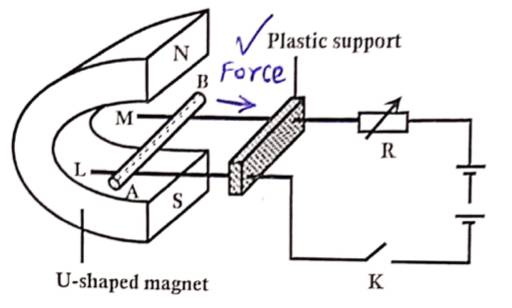
State the conclusion the student made. (1 mark) - Figure 3 shows a copper rod AB lying across two metal rods L and M which are fixed onto a plastic support and also connected to a battery.
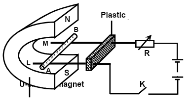
Figure 3- Indicate on the diagram the direction of force experienced on the copper rod AB. (1 mark)
- State the direction of force on copper rod AB if the direction of both current and magnetic field are reversed simultaneously. (1 mark)
- State one way of increasing the force on the copper rod AB. (1 mark)
- State one advantage and one disadvantage of using a convex mirror as a driving mirror. (2 marks)
- Give a reason why a pinhole camera forms a blurred image of an object in front of it if the diameter of the pinhole is reduced to less than 1.00mm . (1 mark)
- Figure 5 below shows a ferromagnetic material PQ being magnetized.
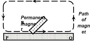
Figure 5-
- State the method of magnetization being used. (1 mark)
- State the pole acquired at P. (1 mark)
- The figure below shows how a distant object is focused in a defective eye.
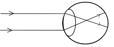
- State the nature of the defect. (1mark)
- On the same diagram, sketch the appropriate lens to correct the defect and sketch rays to show the effect of the lens. (2 marks)
-
SECTION B (55 MARKS).
Answer All the questions in this section in the spaces provided.
-
- When current flows through a coil of nichrome wire in an electrical circuit, the wire becomes very hot.
- Give a reason why the nichrome wire becomes very hot. (1 mark)
- Give a reason why heat is produced only across nichrome wire and not \across other devices in the circuit. (1 mark)
- State one factor that determines the amount of electrical energy converted to heat energy by nichrome wire. (1 mark)
- Figure 6 shows a workman using a cordless electric drill.
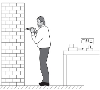
Figure 6
The motor of the drill is powered by a rechargeable battery with an e.m.f. of 23 V. When the drill is used, the power supplied to the motor is 550 W. The workman uses the drill for 1 hour and 30 minutes. Calculate;- The electrical energy supplied to the motor. (3 marks)
- The charge that the battery supplies. (3 marks)
- When current flows through a coil of nichrome wire in an electrical circuit, the wire becomes very hot.
-
-
- Distinguish between a transverse wave and a longitudinal wave. (1 mark)
- State one example of a transverse wave and a longitudinal wave. (2 marks)
- Transverse wave: …………………………………………………………………………
- Longitudinal wave: ………………………………………………………………………
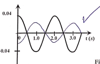
- Figure 7 (a) shows a wave profile for a pendulum bob X released from point P and allowed to swing through Q to R and back a number of times as shown in Figure 7 (b).
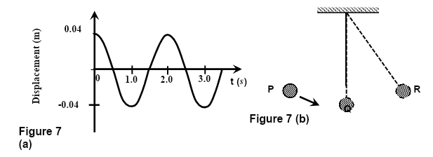
- Determine the amplitude of the wave. (1 mark)
- Calculate the frequency of the wave. (3 marks)
- Sketch a wave profile on the same axes for a similar pendulum bob Y released from point R and oscillating on its own path through Q to P and back a number of times at the same frequency but with half-amplitude as the pendulum bob X. (2 marks)
- In an experiment to observe the interference of light waves, a double slit was placed close to the source of monochromatic light as shown in Figure 8.
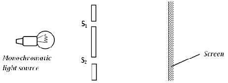
Figure 8- State one condition for interference to occur. (1 mark)
- State the function of the double slit. (1 mark)
- State the observation made on the screen. (1 mark)
- Explain the observation made on the screen. (2 marks)
- State what would happen if the monochromatic light source was replaced with white light source. (1 mark)
-
-
- Define critical angle. (1 mark)
- There are two conditions necessary for total internal reflection to occur. One is that the ray of light must be moving from an optically denser medium to a rarer medium. State the other condition.
(1 mark) - Figure 9 shows the interface between water and diamond.

Figure 9- Draw on the figure a ray diagram to illustrate the critical angle C. (2 marks)
- Calculate the critical angle C given that n = 4 and n =2.42. (3 marks)
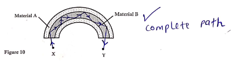
- Figure 10 shows a small piece of an optical fibre cable.
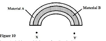
- State which material has a higher refractive index. (1 mark)
- A ray of light enters the optical fibre at X and emerges from Y.
- Sketch the path of the ray through the optical fibre. (1 mark)
- State the reason why light travels through the fibre as in (i) above. (1 mark)
- State one advantage of optical fibre over conventional copper cables as used in telecommunication. (1 mark)
- Apart from its use in telecommunication, state any other application of optical fibre cable.
(1 mark)
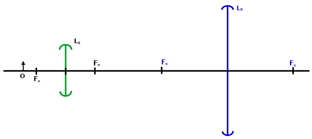
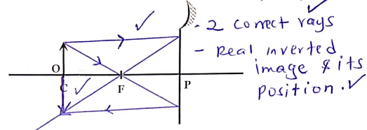
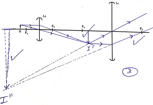
- The diagram shows an arrangement of lenses; Lo and Le used in a compound microscope F0 and Fe are principal foci of L0 and Le respectively. Draw the rays to show how the final image is formed in the microscope. (3 marks)
-
- Define electromotive force (e.m.f) of a cell. (1 mark)
- Figure 11 shows ammeters, resistors and a voltmeter connected to a battery of e.m.f and internal resistance of 0.25 . The reading of ammeter 2 is 2.0 A.
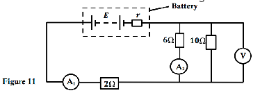
Calculate the;- Total resistance of the circuit. (2 marks)
- Voltmeter reading. (3 marks)
- Reading of ammeter A1 . (1 mark
- e.m.f, E of the battery. (2 marks)
-
- Define capacitance of a capacitor. (1 mark)
- Figure 12 shows three capacitors connected to a battery of voltage 12 .
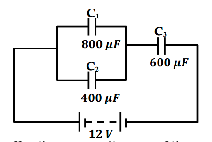
Figure 12- Calculate the effective capacitance of the arrangement. (2 marks)
- Calculate the charge on the 6 μF capacitor. (3 marks)
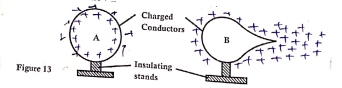
- The conductors A and B in Figure 13 are positively charged and each placed on insulating stands. Show the distribution of charges on conductors A and B. (2 marks)
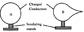
Figure 13
MARKING SCHEME
- θ = 180 − (40 + 90)
θ = 50° -
- Accumulation of hydrogen gas bubbles around the copper plate .(positive plate)
- Local action
- n = C/V
1.5 = 3.0 × 10⁸
V
V = m/s
t = d/v = 0.2
2 × 10⁸
t = 1.0 × 10⁻⁹s - Increase in density
-
- W = I2RT = (Q/t)2 × R × t
W = (240 × 10¯⁶)² × 4000
2 × 60
W = 1.92 × 10⁻⁶ - Radio signals are transmitted by longer wavelength radio waves which are easily diffracted over the hills than shorter wavelength radio waves used to transmit TV signals.
- Magnetic mattractive forces is strongest at the poles.
-
-
- Direction of force remains unchanged. Moves towards the plastic support
-
- Increasing the amount of current
- Using a stronger magnet.
-
-
- Advantage: Gives upright images regardless of the object distances
- Disadvantage: Gives diminished images giving a false impression that the object behind is far.
- Light is diffracted as it mpasses through the pinhole ,hence forming many overlapping images on the screen
-
-
- Single stroke method.
- North pole.
-
- Myopia/ short sightedness
-
6
-
-
-
- Electrical energy mis converted to heat by nichrome wire. The kinetic energy of electrons is converted to heat energy as they collide with atoms in the wire.
- Nichrome wire has higher resistance than the other devices hence more electrical energy is converted to heat energy.
-
- Time taken for current to flow.
- Resistance of wire.
- Amount of current flowing through the wire.
-
- E = Pt = 550 × 90 × 60
= 2.97 × 10⁶J - W = QV
Q = W/V
2.97 × 10⁶
23
Q = 1.291 × 10⁵C
- E = Pt = 550 × 90 × 60
-
-
-
- Transverse wave is a wave whose displacement of particle is perpendicular to the direction of wave motion while longitudinal wave is a wave whose displacement of particles is parallel to the direction of wave motion.
-
- Any electromagnetic wave i.e light
- Sound waves
-
- 0.04m
- f = 1/T
f = 1/2
= 0.5HZ -
-
- The two waves must be coherent
- Acts as coherent sources of light
- Alternate bright and dark fringes are seen on the screen
- Bright fringes are formed when two light waves in phase undergo constructive interference while dark fringes are formed when two light waves out of phase undergo destructive interference
- Interference pattern would disappear. rej. No interference occur
-
-
- Angle of incidence in the optically denser medium for which the angle of refraction in optically less dense medium is 90°
- Angle of incidence in the optically denser medium must be greater than critical angle.
-
 Correct path of ray showing angle C
- wnd = nd
nw
= 2.4z
4/3
wnd = 1.815
Sin C = 1/n
Sin C = 1
1.815
C = Sin−1 (0.5510)
C = 33.43°
-
- Material B
-
-
- Light undergoes repeated total internal reflection
-
-
- Have a lighter carrying capacity
- They are lighter and thinner than copper cables hence easy to install.
- Optical fibre
- They are secure since the information on transit cannot be tapped.
- Used in medicine to view internal organs of the body as with the endoscope.
-
-
- e.m.f is the voltage across the terminals of a cell in an open circuit (i.e when the cell is not supplying current).
-
- RT = r + R1 + R₁R₃
R2+R3
RT = 0.25 + 2 + 6 × 10
6 + 10
RT = 0.25 + 2 + 3.75
RT = 6Ω - V = 1R
2 × 6
= 12V - I10η = 12/10 = 1.2A
Total current = 2.0 + 1.2
= 3.2 A - E = I (R + r)
E = 3.2 × 6
E = 19.2v
- RT = r + R1 + R₁R₃
-
- Is the charge stored per unit voltage.
-
- Parallel combination
800 + 400 = 1200μF
CT = 1200 × 600
1200 + 600
CT = 400μF - Q = CTV
= 400 × 10−6 × 12
= 4800μC or 4.8 × 10⁻³C
- Parallel combination
-
Join our whatsapp group for latest updates
Tap Here to Download for 50/-
Get on WhatsApp for 50/-
Download Physics Paper 2 Questions and Answers - Momaliche Pre Mock Exams 2023.
Tap Here to Download for 50/-
Get on WhatsApp for 50/-
Why download?
- ✔ To read offline at any time.
- ✔ To Print at your convenience
- ✔ Share Easily with Friends / Students