
QUESTIONS
STATION 1
INSTRUCTIONS
Figure 1 shows parts of a fan engine.
- In the space provided, sketch in good proportion the assembled engine. (7 marks)
- Label six parts. (3 marks)
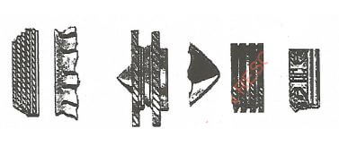
Figure 1
STATION 2
INSTRUCTIONS
Using the tools, equipment and materials provided, make the drive key as shown in figure 2. (10 marks)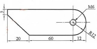
Figure 2
STATION 3
INSTRUCTIONS
Using the tools and components provided, carry out the following tasks:
-
- Check and record the block top surface for warpage gap and condition.
Gap size ................................................................................
Condition................................................................................ - Name the tools used.
Tools...................................................................................... - State one safety precaution to observe in (a)(i).(3 marks)
- Check and record the block top surface for warpage gap and condition.
-
- Check and record the condition of the cylinder wall.
Condition ...................................................................................... - Give the recommendation based on the results in (b)i) above.
Recommendations...........................................................................(2 marks)
- Check and record the condition of the cylinder wall.
-
- Measure and record the internal diameter of the bore at points X, Y and Z.
X...............................Y................................ Z ..................................(3 marks) - From the size of diameters in (c)(i) above, determine the size of the bore and cylindricity.
Bore.......................................Cylindricity..........................................(1 mark) - Basing on the results in (c)(i) and (c)(ii) above, give recommendations. (1 mark)
- Measure and record the internal diameter of the bore at points X, Y and Z.
STATION 4
INSTRUCTIONS
- Identify and state the application of each of the parts of aircraft hydraulic system labelled 1-4.
Complete the table provided.
(4 marks)Part Identification Application 1 2 3 4 - Measure and record the size of pipes labelled 5 and 6.
- Size of pipe 5..............................
- Size of paper 6 ..........................(2 marks)
- Identify two defects on each of the pipes in (b) above.
- Defects on pipe 5............................
- Defects on pipe 6.c.........................(2 marks)
- State two serviceability checks that must be carried out on item 6 before fitting on an aircraft.(1 mark)
- Identify the system where each of the pipes in (b) are used.
Pipe 5 ..........................................................
Pipe 6..........................................................(1 mark)
STATION 5
INSTRUCTIONS
Using the materials and equipment provided, carry out the following tasks:
- Switch on the air compressor and allow pressure to build up to about 10 bars. Open the air flow valve marked R slowly and hold the hose labelled T vertically so that the stream of gases are directed straight up. Let the examiner check the set up.(1 mark)
-
- Release the ping-pong ball marked nozzle. Record your observations.
into the stream of air 30 centimetres from the
Observations .................................................................... - Slowly tip the nose so that air shoots out an angle. Record the observations
Observations ............................................................... - Repeat (b)(ii) with increased air pressure. Record the observation.
Observations .........................................................................
State three reasons behind your observation in (b)(i) to (b)(iii).
Reasons.....................................................(6 marks)
- Release the ping-pong ball marked nozzle. Record your observations.
- State:
- Where the principle is applicable in flight.
Application ............................................................... - Two weather factors that can affect the observations in (b).
Factors:- ..........................................................
- ..........................................................(3 marks)
- Where the principle is applicable in flight.
STATION 6
INSTRUCTIONS
An aircraft is to be flown from point E to P eastwards. The wind speed at the altitude of the intended flight is 45 knots from the northeast, while the true airspeed of the aeroplane is 120 knots.
Using the drawing instruments and the plain paper provided, carry out the following tasks.
- Construct in four steps a wind triangle for navigation purposes.(8 marks)
- Measure and record the true heading by direct measurement and wind correction angle.
- Direct measurement ..........................................................
- Wind correction angle ..........................................................(2 marks)
STATION 7
INSTRUCTIONS
- Drop the ball marked Z in the jar labelled 10.
- Record your observation
Observation...................................................... - State the reasons behind your observation
Reasons .......................................................... - Explain the principle behind your observation
Principle.......................................................... - State two areas where applicable in an aircraft.
Applications ..........................................................(4 marks)
- Record your observation
- Using the materials provided, make each of the following aircraft wing plan forms:
- Elliptical
- Delta
- Sweepback
- Rectangular (4 marks)
- State one application for each wing plan form in (b).
Elliptical ..........................................................
Delta..........................................................
Sweepback ..........................................................
Rectangular .......................................................... (2 marks)
STATION 8
INSTRUCTIONS
- Study the instrument labelled 1 and identify the following:
- Principle of operation
- Aircraft system used(1 mark)
- Using the pump and instrument assemblies labelled 2 and 3 carry out the following tasks.
- Connect the pump to the instrument assembly labelled 1 and slowly, pressurise.
Record the observation.
Observation .......................................................... - State the reason behind the observation.
Reason ..................................................... - State the principle behind the observation.
Principle.......................................................... - State one application in an aircraft.
Application............................................................(4 marks)
- Connect the pump to the instrument assembly labelled 1 and slowly, pressurise.
-
- Repeat (a)(i) using the assembly labelled 2. Record the observation.
Observation.......................................................... - State the reason behind the observation.
Reason.......................................................... - State the principle behind the observation.
Principle.......................................................... - State one application in an aircraft.
Application..........................................................(4 marks)
- Repeat (a)(i) using the assembly labelled 2. Record the observation.
- Compare the pressure requirements from observations A and B.(1 mark)
Comparison..........................................................
STATION 9
INSTRUCTIONS
Using tools and materials provided, carry out the tests listed on the materials labelled T and V and complete the table below.
| Test | Material T | Material V |
| colour | ||
| breaking | ||
| cutting | ||
| burning | ||
| bending |
(10 marks)
STATION 10
INSTRUCTIONS
Using tools, equipment and materials provided construct a circuit that has two cells and two bulbs in series on the bread board provided. (10 marks)
MARKING SCHEME
Station 1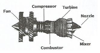
Correct order of assembly 6 marks
Correct labeling 3 marks
Proportionality 1 mark
STATION 3
-
- Check and record the block top surface for war page
Reading - Sample data
Warpage condition - Sample date - The tool used,
Straight edge
Feeler gauge - Make sure that the surface is free from gasket chips and other foreign matters.
- Check and record the block top surface for war page
-
- Check and record the condition of the cylinder walls on the cylinder block provided.
Condition - scratched and worn. - In view of results in b (1) give recommendations.
Recommendation -Scratched and solution is to rebore or replace.
- Check and record the condition of the cylinder walls on the cylinder block provided.
-
- Measure and record on cylinder labelled Wat point x, y and z the internal diameter.
Point x -Sample Data
Point y-Sample Data
Point z-Sample Data - Determine from C (i) the bore and cylindricity
Bore-Sample Data
Cylindricity - Sample Data - In view of results in C (i) and (ii) give recommendations.
Recommendations - Correct the cylinder to an oversize and replace the piston rings if worn beyond 0.001 mm limit.
- Measure and record on cylinder labelled Wat point x, y and z the internal diameter.
STATION 4
-
Part Identification Application 1 Cross Union Forms a four way junction 2 Reducing union Enables pipe of different diameter to be connected 3 Straight bulkhead union Adoption of another threaded nut to attach the union firmly to the wall or bulkhead 4 Nipple Used to correct pipes and units of equal diameter. -
- Size of paper 5 - rigid pipe by external diameter - Sample data
- Size of pipe 6 - Internal diameter ......Sample data
- Defects on 5 :
- Bent
- Threads damaged
Defects on 6
- Porosity
- Broken strands - Check on pipe 6
- Ensure no bulging of ingress of dirt by passing on ball through pipe.
- Externally ensure the damage or signs of broken stands.
- Application
- Pipe 5 - fuel system
- Pipe 6 - hydraulic system
Station 5
-
- The ball will suspend upright by the airflow
- The ball will stay suspended in the airstream.
- The ball will stay suspended in the airstream slightly further away from the Nozzle.
- Reasons
- The pressure acting upon the ball tends to make it suspended in the airstream when airstream pressure increases.
- The fast moving airstream lessens the air pressure on the portion of the ball remaining in the airstream.
- The force of gravity is overcome which results in the ball remaining suspended according to pressure variations.
-
- Generation of lift over an air foil in relationship to the relative airflow.
- Factors
- Change in air density
- Change in temperature
Station 6
-
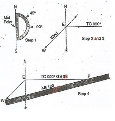
Step 1
Position and protractor - 1 x 1 mvc (NS Line)
Step 2
Direction of wind - 45°
Track - True course 90°
E-point of departure
E point (4x1/2)= 2 marks)
Step 3
Course line from E-Tc090° (1 x 1 = 1 mark)
Step 4- Wind arrow Eat 45° downward
- Identify W-wind line
Determine scale for use with arrow and W and 120 knots dot interception of true course line. - Draw Airspeed (As 120) with point P at intercept (Aircraft position P)
- Ground speed on (TC 090° GS 88) knots
-
- True heading 0.76°
- Wind correction angle 14°
STATION 7
-
- Observation : Ball remains floating but water level rises slightly.
- Reason: Ball displaces its own volume (weight)
- Principle: Up thrust (floatation)
- Application:
- Carburetor
- Fuel tanks quantity
-
- Elliptical - Low speed
- Delta - Very high speed
- Sweep back - High speed
- Rectangular - Low speed
STATION 8
-
- Gyroscopic precision
- Navigation
-
- Observation: The bourdon tube tends to straighten to move the gear mechanism.
- Reason: The outside part of bourdon has a bigger service, area and thus under some pressure, the bourdon tube tends to straighten.
- Principle : Area differential.
- Application: System pressure indication
-
- Observation: The bellows expand and contract, moving the gear mechanism.
- Reason: The bellow expand under pressure but remains stationery under static pressure condition.
- Principle-Pressure differential
- Application - Airspeed indiction
- Comparison ......A requires more pressure to move the gear assembly than B.
STATION 9
| Test | Material T | Material V |
| colour | Transparent/colourless | Tint background viewed from edge |
| breaking | Snaps with clean edge | Tears with ragged edge. |
| cutting | Easily cut with standard tools | Cuts easily with scissors |
| burning | Burns slowly with clear smokeless flame | Smoky flame and melts |
| bending | Brittle springy and only bends slightly | Easily bend and flexible |
Download KCSE 2018 Aviation Technology Paper 2 with Marking Scheme.
Tap Here to Download for 50/-
Get on WhatsApp for 50/-
Why download?
- ✔ To read offline at any time.
- ✔ To Print at your convenience
- ✔ Share Easily with Friends / Students