
QUESTIONS
EXERCISE 1
- Using the materials, equipment and measuring instruments provided, perform the following tasks:
- Connect the circuit as shown in Figure 1. (3 marks)
Let the examiner check your work.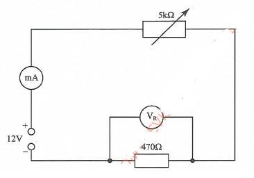
Figure 1 - Turn the power ON and adjust the potentiometer to obtain each of the voltages (VR). Shown in Table 1. In each case read and record the corresponding current I. (6 marks)
Table 1
VR I(mA) POWER(mW) 3 4 5 6 7 8 - For each value of VR, calculate the power dissipated in the 4700 resistor and complete the table.(6 marks)
- Using the values in Table 1, draw the graph of power against voltage VK. (4 marks)
- State two applications of the circuit.(1 mark)
- Connect the circuit as shown in Figure 1. (3 marks)
EXERCISE 2
2. Use the tools, equipment and materials provided to make an electronic circuit casing shown in Figure 2. (20 marks)
Let the examiner check your work.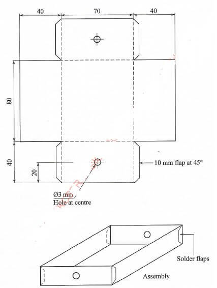
Figure 2
EXERCISE 3
- Using the components and equipment provided, connect the circuit as shown in Figure 3.
Let the examiner check your work.(6 marks)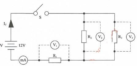
Figure 3 - Put ON the power supply. Close switch S, measure and record current through the following resistors:(3 marks)
R1 = .............................................
R2 = .............................................
R3 = ............................................. - Measure the total circuit current, IT. (2 marks)
IT = ............................................. - Measure and record the voltages across the following resistors: (6 marks)
R1 = .............................................
R2 = .............................................
R3 = ............................................. - Using the values in (c) and (d) above, calculate the value of the resistors: (3 marks)
R1 = .............................................
R2 = .............................................
R3 = .............................................
RT = .............................................
EXERCISE 4
4. Figure 4 shows a block diagram of a prefabricated electronic circuit.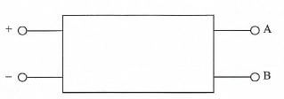
Figure 4
Using the equipment and accessories provided, perform the following tasks:
- Connect the circuit to the power supply through the PBNO switch provided.
Let the examiner check your work.(2 marks) - Press and hold the PBNO switch for about 10 seconds and describe the behaviour of the LEDS:(1 mark)
-
- Connect the 10kΩ resistor at A and B.
Let the examiner check your work.(1 mark) - Press and hold the switch. Count the number of times each LED flashes in one minute:
RED.............................................
GREEN.............................................(4 marks)
- Connect the 10kΩ resistor at A and B.
- Draw the schematic diagram of the circuit.(10 marks)
- State:
- the name of the circuit(1 mark)
- application of the circuit.(1 mark)
EXERCISE 5
5. Figure 5 shows a layout of a final circuit, using PVC conduit wiring system, install the circuit such that the lamp is controlled by the one way switch.(20 marks)
Let the examiner check your work.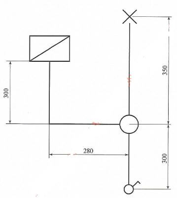
Figure 5
MARKING SCHEME
EXERCISE 1
| Areas to be marked | Maximum Score | Candidate Score | |
| a | Marked at the examination centre | 3 | |
| b | Correct table of values of current (6x1) | 6 | |
| c | Correct table of values of power (6x1) | 6 | |
| d | (i) Labelling of axes correctly (2 x 1/2) | 1 | |
| (ii) Plotting the graph correctly (6 x 1/2) | 3 | ||
| e | Two applications: (i) Maximum power transfers to load (ii). Impedance matching (2 x 1/2) |
1 | |
| TOTAL | 20 marks |
EXERCISE 3
| Areas to be marked | Maximum Score | Candidate Score | |
| a | Marked at the examination centre | 6 | |
| b | Correct table of values of current through R1, R2, R3 (3x1) | 3 | |
| c | Total circuit current IT (2x1) | 2 | |
| d | Correct value of voltage across R1, R2, R(3x1) | 3 | |
| e | Correct Calculated values of Ri, Rz, Rz and RT(4x11/2) | 6 | |
| TOTAL | 20 marks |
EXERCISE 4
| Areas to be marked | Maximum Score | Candidate Score | |
| a | (a) and (c) Marked at the examination centre | 3 | |
| b | Behaviour of the LEDs ( The two LEDs glow or flash (2 x 1/2) | 1 | |
| c | (ii) Correct number of times each LED flashes in one minutes (2x2) | 4 | |
| d | Correct Schematic diagram (10x1) | 10 | |
| e | (i) Name of the circuit (1x1) | 1 | |
| (ii) Application of the circuit (1x1) | 1 | ||
| TOTAL | 20 marks |
Join our whatsapp group for latest updates
Tap Here to Download for 50/-
Get on WhatsApp for 50/-
Download KCSE 2018 Electricity Paper 2 with Marking Scheme.
Tap Here to Download for 50/-
Get on WhatsApp for 50/-
Why download?
- ✔ To read offline at any time.
- ✔ To Print at your convenience
- ✔ Share Easily with Friends / Students