
INSTRUCTIONS TO CANDIDATES:-
- Write your Name, Index number, Admission number and school in the spaces provided above.
- This paper consists of two sections; A and B
- Answer all the questions in section A and B in the spaces provided
- All working must be clearly shown.
- Mathematical tables and electronic calculators may be used.
- This paper consist of 19 printed pages. You are advised to ascertain that all pages are printed as indicated.
- Take the earth’s gravitational field strength g = 10 m/s2.
For Examiner’s Use Only:
|
SECTION |
QUESTION |
TOTAL SCORE |
CANDIDATES SCORE |
|
A |
1 – 12 |
25 |
|
|
B |
13 |
10 |
|
|
14 |
9 |
||
|
15 |
8 |
||
|
16 |
9 |
||
|
17 |
9 |
||
|
18 |
10 |
||
|
TOTAL |
|
80 |
QUESTIONS
SECTION A (25 MARKS)
Answer all questions in this section in the spaces provided.
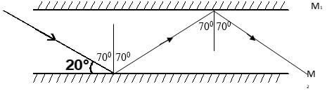
- The diagram below shows two parallel mirrors M1 and M2 and a ray of light being incident on one of the mirrors as shown.
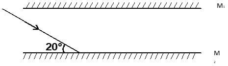
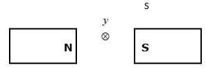
Trace the ray of light through the mirrors and indicate the angle of incidence on M1 (2 mks) - Two pins are hanging from a magnet as shown in the diagram below.
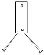
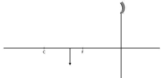
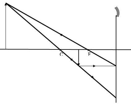
Explain why the pins spread as shown in the diagram. (2mks) - An image I is formed infront of a concave mirror and on the principal axis as shown in the figure below.
- The figure below shows a set up by a student.
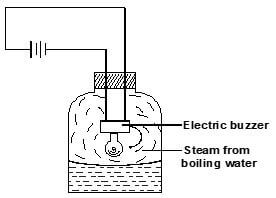
State and explain what happens to the sound from the buzzer as the bottle and its contents are cooled to 0°C. (2 mks) - Arrange the following waves in order of decreasing wavelength. (1mk)
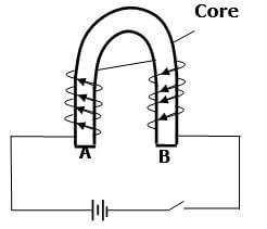
Infrared, X-rays, Microwaves, Radio waves, Red light. - Figure below shows an incomplete circuit of an electromagnet.
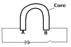
Complete the circuit by drawing the windings on the two arms of the core such that A and B are both North poles when the switch is closed. (1mk) - Figure represents a step in charging a material B negatively by induction.
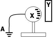
- What is the charge on Y? (1mk)
- Explain what happens at A. (1mk)
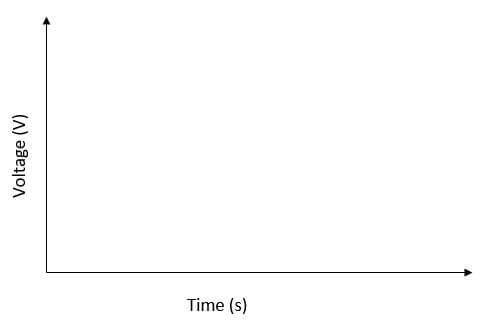
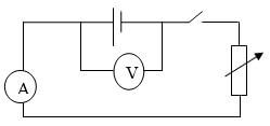
- The graph below shows the variation of p.d. (V) across the terminals of a cell and current drawn from the cell.
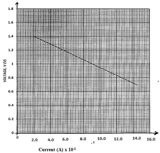
- Use the graph to determine the electromotive force (emf) of the cell. (1mk)
- Draw a circuit diagram that may be used to obtain the values plotted in the graph. (2mk)
- A vibrator is sending out eight ripples per second across a water tank. The ripples are observed to be 4cm apart. Calculate the velocity of the ripples. (3mks)
- The figure below shows part of electric cooker coil.
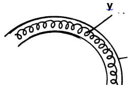
- Why is the material labeled Y coiled? (1mk)
- State the property of material Y that makes it suitable for its use. (1mk)
- An immersion heater rated 1500W is used continuously for 30 minutes per hour per day. Calculate the cost of electricity per week if the rate is Ksh. 6.70 per unit. (2mks)
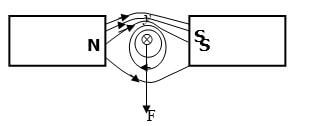
- Fig below shows a conductor y placed in a magnetic field. The conductor carries a current flowing into the paper.
- Sketch the resultant magnetic field between the poles of the bar-magnet. (1mk)
- Show on the diagram the direction of the force, F acting on the conductor (1mk)
SECTION B (55 MARKS)
Answer all questions in this section in the spaces provided.
-
- Figure below shows the path of light through a transparent material placed in air.
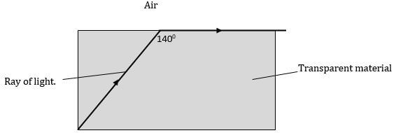
- Give a reason why the above ray is not refracted at the interface of air and the transparent material as shown in the diagram. (1mk)
- Calculate the refractive index of the transparent material. (3mks)
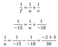
- An image is formed 10cm in front of a concave lens of focal length 15cm. calculate the position of the object in respect to the lens. (3mks)
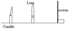
- You are provided with the following apparatus to determine the focal length of a lens.
- A lit candle.
- A white screen.
- A metre rule.
With a aid of a labelled diagram, describe the procedure you would follow to determine the focal length of the lens. (3mks)
- Figure below shows the path of light through a transparent material placed in air.
-
- The figure below shows metal plates X and Y each fixed to an insulated stand. X is charged and Y is earthed. X is connected to an uncharged electroscope with a conductor.
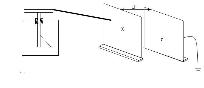
If plate Y is moved away from plate X,- State what happens to the amount of charge on the plates. (1mk)
- State and explain the observation made. (3mks)
- The figure below shows an arrangement of capacitors connected to a 12V dc supply.
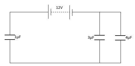
Determine:- The total capacitance of the arrangement. (2mks)
- The voltage across the 3μF capacitor. (3mks)
- The figure below shows metal plates X and Y each fixed to an insulated stand. X is charged and Y is earthed. X is connected to an uncharged electroscope with a conductor.
-
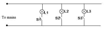
- The figure below shows an attempt to supply each of the three lamps L1, L2 and L3 with a switch.
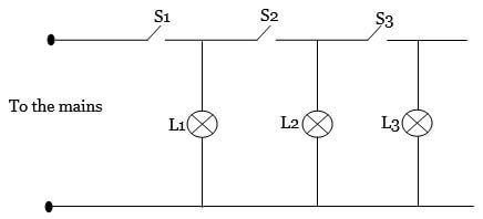
- Give a reason why this is a poor connection. (1mk)
- Redraw the diagram to show the correct positioning of the switches. (1mk)
- A wire placed between the pole of two permanent magnets is connected to a galvanometer as shown below.
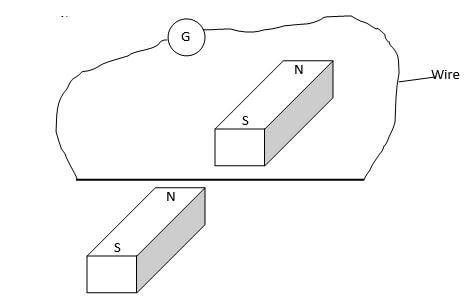
- State what is observed when the wire is moved up and down. (2mks)
- Suggest two ways of increasing the magnitude of the effect you have stated in (i) above. (2mks)
- The figure below shows a simple transformer. Study it and answer the questions that follow.
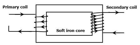
State and explain which coils are thicker. (2mks)
- The figure below shows an attempt to supply each of the three lamps L1, L2 and L3 with a switch.
-
- The figure below shows Zinc plate placed on the cap of a negatively charged electroscope.
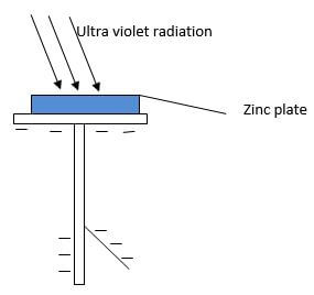
Ultraviolet radiation is made to fall on the plate as shown on the diagram.- What happens to the leaf of the electroscope? (1mk)
- What would happen if radiation was red light? (1mk)
- In an experiment to find the relationship between frequency of a radiation and kinetic energy of the photoelectrons in a photoelectric device, the following graph was obtained.
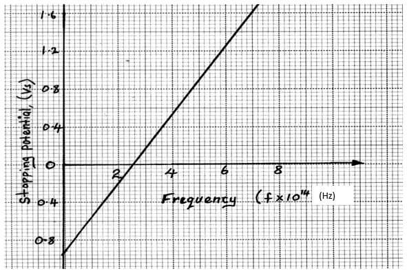
Use the graph to determine the Planck’s constant h. (3mks) - Figure below shows the features of an X-ray tube.
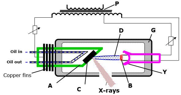
- Explain the function of part labelled P. (1mk)
- Explain why the part labelled C gets very hot during production of X-rays. (2mks)
- Explain what is done to produce X-rays of shorter wavelength using the above X-ray tube. (1mk)
- The figure below shows Zinc plate placed on the cap of a negatively charged electroscope.
-
- The figure below shows monochromatic source of light L behind a barrier with a single slit S placed behind another barrier with two identical slits S1 and S2. A screen PQ is placed in position as shown.
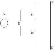
- What is the significance of S1 and S2? (1 mk)
- Explain what is observed on screen PQ. (2 mks)
- Waves pass from deep water to shallow water and refraction occurs.
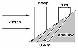
Calculate the speed of the waves in the shallow water. (2 mks) - The figure below shows an a.c. signal on the screen of a Cathode Ray Oscilloscope.
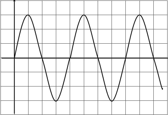
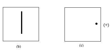
Determine the frequency of the signal given that the time base is set at 10ms/division. (2mks) - Diagram (a) below shows the position of the bright spot on the screen of a C.R.O. when there is no signal on both Y and X plates.
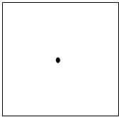
Indicate on the diagram (b) below what is observed on the display screen when the Y-plate is connected to a.c. signal and for (c) when X-plate is connected to a d.c. signal. (2mks)
b).
c).
- The figure below shows monochromatic source of light L behind a barrier with a single slit S placed behind another barrier with two identical slits S1 and S2. A screen PQ is placed in position as shown.
-
- The following reaction is part of a radioactive series.
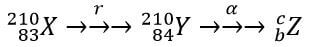
- Identify the radiation r. (1mk)
- Determine the value of c. (1mk)
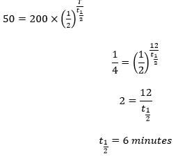
- At a certain instant the corrected count-rate registered on a detector placed close to an α-particle emitter is 200 per second and this falls to 50 per second in 12 minutes. Determine the half life of the source. (3mks)
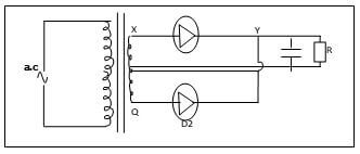
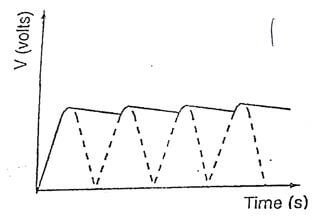
- Study the rectification circuit below and use it to answer questions that follow.
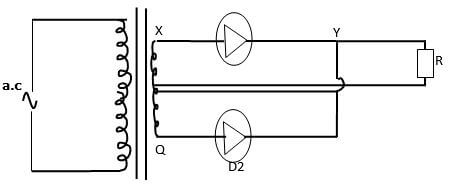
- Briefly explain how the circuit works to rectify the alternating current. (3mks)
- Show on the diagram how a capacitor should be connected to smooth the output voltage. (1mk)
- In the grid provided, sketch a curve of smoothed output voltage against time. (1mk)
- The following reaction is part of a radioactive series.
MARKING SCHEME
|
SECTION A (25 marks) |
|||
|
1. |
|
1 1 |
CORRECT RAYS Correct angles |
|
2 |
The ends of the pin acquire the same polarity thus they repel each other. |
1 1 |
|
|
3. |
 |
2 |
Correct rays @ 1mk Position and nature of image (real, upright,magnified) |
|
4. |
The sound becomes faint/ magnitude of sound reduces On cooling the partial vacuum is created which minimizes the transmission of sound which requires a medium. |
1 1 |
|
|
5. |
Radio waves , Microwaves, Infrared, X-rays,Red light. |
1 |
|
|
6. |
|
1 |
Tied Both must be correct. |
|
7. |
|
1 1 |
|
|
8. |
|
1 1 1 |
Must extrapolate. If not deny. Correct symbols Correct arrangement (both marks tied) |
|
9. |
V =fλ |
1 1 1 |
Formula Substitution Answer |
|
10. |
|
1 1 |
|
|
11. |
cost = 1500 x 30 x 6.70 |
1 1 |
Evaluation Answer (check units) |
|
12. |
 |
1 1 |
Correct magnetic field pattern Direction of the force |
|
SECTION B (55 marks) |
|||
|
13. |
|
1 1 1 1 1 1 1 1 1 1 |
Formula Substitution Answer Formula Substitution Answer Diagram |
|
10 |
|||
|
14. |
|
1 1 1 1 1 1 1 1 1 |
|
|
09 |
|||
|
15. |
|
1 1 1 1 2 1 1 |
|
|
08 |
|||
|
16. |
|
1 1 1 1 1 1 1 1 1 |
|
|
09 |
|||
|
17. |
|
1 1 1 1 1 1 1 1 1 |
|
|
09 |
|||
|
18. |
|
1 1 1 1 1 1 1 1 1 |
Must show working Look out for alternative method Capacitor across the load |
Download Physics Paper 2 Questions and Answers - Mincks Group of Schools Mock Examinations 2022.
Tap Here to Download for 50/-
Get on WhatsApp for 50/-
Why download?
- ✔ To read offline at any time.
- ✔ To Print at your convenience
- ✔ Share Easily with Friends / Students