
INSTRUCTIONS TO CANDIDATE
- Answer ALL the questions in the spaces provided in the question paper.
- You are supposed to spend the first 15 minutes of the 2½ hours allowed for this paper reading the whole paper carefully before commencing your work.
- Marks are given for a clear record of the observations actually made, their suitability, accuracy and the use made of them.
- Candidates are advised to record their observations as soon as they are made.
- Non-programmable silent electronic calculators may be used.
- Candidates should answer the questions in English.
QUESTION 1
You are provided with the following:
- A metre rule
- A spring balance
- A mass M
- Stand
- Knife edge support.
- Two light strings about 10cm long.
Proceed as follows:
- Use the spring balance to determine weight of mass M ………………N. ( 1mk)
- Using the string provided make two loops to be used as hooks L1 and L2 in the diagram.
- Suspended the spring balance from a clamp and using one loop to support the rule from the spring so that the loop L2 is on 85cm mark.
- Support the other end of the rule with a knife edge at the 10cm mark so that the rule is horizontal.
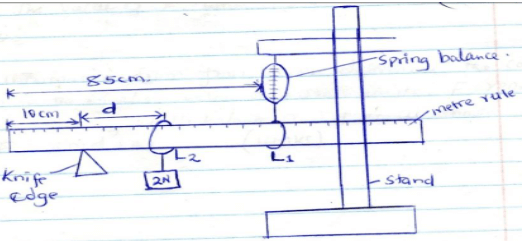
- Using loop 1 suspended the mass M at a distance d=10cm from the knife edge as shown and take the reading of the spring balance, record the results in table 1.
- Adjust the distance, d, to 20cm, 30cm e.t.c and each time recording the reading of the balance to complete the table.
Table 1
Distance (d)cm 10.0 20.0 30.0 40.0 50.0 60.0 70.0 Distance (d) m Force (N) - Plot a graph of force F against distance d(m) (5 marks)
- From your graph determine:
- The slope (3mks)
- The value of F when d=0 (2mks)
- Using the information from your graph, determine the constant k and n in the equation below and indicate their units, F= 2nd +40k.
- N (3mks)
- K (3mks)
QUESTION 2
You are provide with the following
- A nichrome wire mounted on a millimeter scale labelled AB
- A galvanometer.
- Jockey
- A carbon resistor labelled X .
- 8 Connecting wires, 4 with crocodile clips at both ends.
- A resistance wire labelled R mounted on a half meter rule
- Ammeter
- Voltmeter
- One dry cell in a cell holder
- Micrometer screw gauge
Proceed as follows:
- Set up the circuit as shown below.
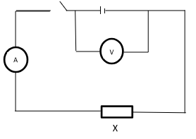
- Record the voltmeter reading when the switch is open.
E = ………………………………………………………… (1mark) - Close the switch and record the voltmeter and ammeter readings V and I.
V = ………………………………………………………… (1mark)
I = …………………………………………………………… (1mark) - Explain why V is less than E . (1mark)
- Now connect the voltmeter across the carbon resistor X and record voltmeter reading V1 when the switch is on.
V1 = …………………………………………………………. (1mark) - Determine X given that X = V1 (1mark)
I
- Record the voltmeter reading when the switch is open.
- Using the micrometre screw gauge, measure and record the diameter D of the resistance wire R provided
D =……………………………………………………m (1mark) - Now connect another circuit as shown in the figure below.
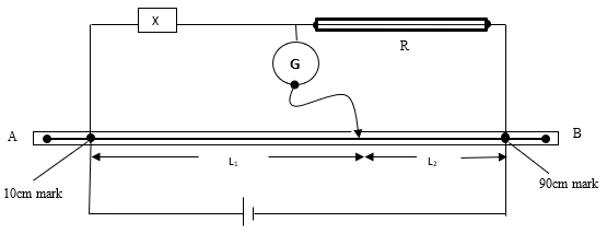
Touch the 10cm mark and the 90 cm mark and see that the galvanometer deflects in opposite direction in each case.- Move the sliding jockey along the resistance wire AB and note the length L1 and L2 where the galvanometer pointer points at the zero mark. Record the values of L1 and L2.
L1 =…………………………………………………………………m (1mark)
L2 =………………………………………………………………… m (1mark) - Determine the resistance of the resistance wire R using the relationship, (2marks)
R = X
L1 L2 - Determine the resistance of the wire R per metre. (1 mark)
- Given that, R = 0.1114S determine the value of S, where R is the resistance per metre. (3mark)
D2
- Move the sliding jockey along the resistance wire AB and note the length L1 and L2 where the galvanometer pointer points at the zero mark. Record the values of L1 and L2.
PART B
You are provided with the following;
- Soft board
- Vernier calipers.
- Rectangular Glass block
- Four optical pins.
- Plain sheet of paper.
- Two thumb tacks
- Protractor
Procedure;
- Measure and record the width t of the glass block using the vernier calipers provided.
t = ……………………………………………… (m) (1 mark) - Fix the white plain paper on the soft board using the two thumb tacks.
- Place the glass bock on the paper, trace its outline and label it ABCD, as shown.
- Remove the glass block and draw a normal, say at point O.
- Draw a line making an angle of 30° with the normal to represent the incident ray.
- Replace the glass block carefully to its original position.
- Fix two pins P1 and P2 on the line in such a way that they are vertical and at least 4cm apart.
- Looking through the glass block through face AB, fix two pins P3 and P4 so that they are exactly in line with the P1 and P2. Mark the positions of P3 and P4
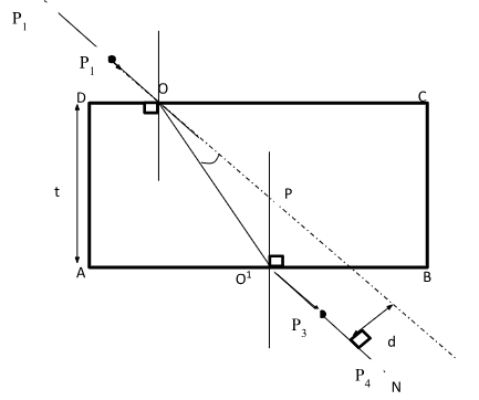
- Join P3 and P4 and produce the line to meet face AB of the block at O1. Join O and O1.
Measure angle O1OP.
Also, Measure angle OO1P.
O1OP = ………………………………………………………………………(1mark)
OO1P = …………………………………………………………………………(1mark) - Measure the perpendicular distance d from the line O1N to OP produced.
d = ………………………………………………………………… (m) (1mark) - Determine t1 given that, t1 = dcos angle(OO1P) (3marks)
sin angle (O1OP) - How do the values of t and t1 compare. (1mark)
NB. The worksheet should be handed in with the question paper.
- Join P3 and P4 and produce the line to meet face AB of the block at O1. Join O and O1.
CONFIDENTIAL
Question 1
Provide each candidate with the following apparatus.
- A metre rule
- A spring balance ( RANGE ABOVE 2.5 N)
- A mass of 200g (2N) with a hook or (two 100g masses) labeled M
- A complete retort stand
- Knife edge support at least 7 cm high
- Two light strings about 10cm long.
Question 2
- A nichrome wire mounted on a millimeter scale labelled AB(use a wire of diameter 0.36mm)
- A galvanometer.
- Jockey
- A carbon resistor labelled X .(10 ohm carbon resistor)
- 8 Connecting wires, 4 with crocodile clips at both ends.
- A resistance wire labelled R mounted on a half meter rule(use a wire of diameter 0.36mm fixed on half metre rule) using cello tape.
- Ammeter (range 0-1)
- Voltmeter (range 0-5 or 0-2.5)
- One dry cell in a cell holder
- Micrometer screw gauge
- Soft board
- Vernier calipers.
- Rectangular Glass block of width 6.50 cm
- Four optical pins.
- Plain sheet of paper.
- Two thumb tacks
- Protractor
MARKING SCHEME
QUESTION 1
You are provided with the following:
- A metre rule
- A spring balance
- A mass M
- Stand
- Knife edge support.
- Two light strings about 10cm long.
Proceed as follows:
- Use the spring balance to determine weight of mass M ………2N………. ( 1mk)
- Using the string provided make two loops to be used as hooks L1 and L2 in the diagram.
- Suspended the spring balance from a clamp and using one loop to support the rule from the spring so that the loop L2 is on 85cm mark.
- Support the other end of the rule with a knife edge at the 10cm mark so that the rule is horizontal.
- Using loop 1 suspended the mass M at a distance d=10cm from the knife edge as shown and take the reading of the spring balance, record the results in table 1.
- Adjust the distance, d, to 20cm, 30cm e.t.c and each time recording the reading of the balance to complete the table.
Table 1
Distance (d)cm 10.0 20.0 30.0 40.0 50.0 60.0 70.0 Distance (d) m Force (N) - Plot a graph of force F against distance d(m) (5 marks)
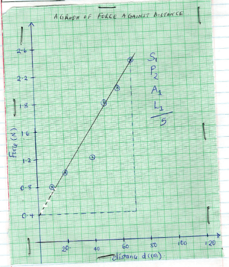
- From your graph determine:
- The slope (3mks)
Points (0, 0.4) and m(70, 2.4)
Slope = 2.4 − 0.4
(70 − 0)
= 2.857N/cm or 2.857 × 10⁻² N/m - The value of F when d=0 (2mks)
When D = 0 force F = 0.4N i.e y - intercept
1mk for identify it's a value for y - intercept
- The slope (3mks)
- Using the information from your graph, determine the constant k and n in the equation below and indicate their units, F= 2nd +40k.
- N (3mks)
Comparing y = mx + c with F = 2md + 40k
Then gradient = 2m
2.857 = 2m
M = 2.857
2
=1.4285 - K (3mks)
Y – intercept = 40k
0.4 = 40k
K = 0.4
40
= 0.01
- N (3mks)
QUESTION 2
You are provide with the following
- A nichrome wire mounted on a millimeter scale labelled AB
- A galvanometer.
- Jockey
- A carbon resistor labelled X .
- 8 Connecting wires, 4 with crocodile clips at both ends.
- A resistance wire labelled R mounted on a half meter rule
- Ammeter
- Voltmeter
- One dry cell in a cell holder
- Micrometer screw gauge
Proceed as follows:
- Set up the circuit as shown below.
- Record the voltmeter reading when the switch is open.
E = ………………1.6v ± 0.2v………………………………………… (1mark) - Close the switch and record the voltmeter and ammeter readings V and I.
V = …………………1.0v ± 0.2……………………………………… (1mark)
I = ……………0.09A ± 0.02……………………………………………… (1mark) - Explain why V is less than E . (1mark)
- Volts are lost in overcoming the internal resistance.
- Now connect the voltmeter across the carbon resistor X and record voltmeter reading V1 when the switch is on.
V1 = ……………1.0v ± 0.2……………………………………………. (1mark) - Determine X given that X = V1 (1mark)
I
x = 1 = 11.11 (correct substitution)
0.09
- Record the voltmeter reading when the switch is open.
- Using the micrometre screw gauge, measure and record the diameter D of the resistance wire R provided
D =………0.00045 ± 0.00005m……………m (1mark) - Now connect another circuit as shown in the figure below.
Touch the 10cm mark and the 90 cm mark and see that the galvanometer deflects in opposite direction in each case.- Move the sliding jockey along the resistance wire AB and note the length L1 and L2 where the galvanometer pointer points at the zero mark. Record the values of L1 and L2.
L1 =………………0.00035 ± 0.00005m........... (1mark)
L2 =……………0.00045 ± 0.00005m…………… (1mark) - Determine the resistance of the resistance wire R using the relationship, (2marks)
R = X
L1 L2
R = 11.11
0.00035 0.00045
R = 11.11 × 0.00035
0.00045
R = 8.641 ohms
(correct substitution from student work) - Determine the resistance of the wire R per metre. (1 mark)
(correct substitution from student work)
R = 8.641 × 100 ohms per metre
80
= 10.80 ohms per metre - Given that, R = 0.1114S determine the value of S, where R is the resistance per metre. (3mark)
D2
Correct substitution
10.8 = 0.1114S
0.000452
S = 1.963 × 10⁻⁵
- Move the sliding jockey along the resistance wire AB and note the length L1 and L2 where the galvanometer pointer points at the zero mark. Record the values of L1 and L2.
PART B
You are provided with the following;
- Soft board
- Vernier calipers.
- Rectangular Glass block
- Four optical pins.
- Plain sheet of paper.
- Two thumb tacks
- Protractor
Procedure;
- Measure and record the width t of the glass block using the vernier calipers provided.
t = ……………0.065 ± 0.01………………………………… (m) (1 mark) - Fix the white plain paper on the soft board using the two thumb tacks.
- Place the glass bock on the paper, trace its outline and label it ABCD, as shown.
- Remove the glass block and draw a normal, say at point O.
- Draw a line making an angle of 30° with the normal to represent the incident ray.
- Replace the glass block carefully to its original position.
- Fix two pins P1 and P2 on the line in such a way that they are vertical and at least 4cm apart.
- Looking through the glass block through face AB, fix two pins P3 and P4 so that they are exactly in line with the P1 and P2. Mark the positions of P3 and P4
- Join P3 and P4 and produce the line to meet face AB of the block at O1. Join O and O1.
Measure angle O1OP.
Also, Measure angle OO1P.
O1OP = ……………………10° ± 2………………………………………………………(1mark)
OO1P = …………………20° ± 2………………………………………………………(1mark) - Measure the perpendicular distance d from the line O1N to OP produced.
d = ………………0.012 ± 0.002………………………………………………… (m) (1mark) - Determine t1 given that, t1 = dcos angle(OO1P) (3marks)
sin angle (O1OP)
t1 = 0.012 × Cos 10
Sin 20
= 0.0649m - How do the values of t and t1 compare. (1mark)
- They are equal or approximately the same
NB. The worksheet should be handed in with the question paper.
- They are equal or approximately the same
- Join P3 and P4 and produce the line to meet face AB of the block at O1. Join O and O1.
Join our whatsapp group for latest updates
Tap Here to Download for 50/-
Get on WhatsApp for 50/-
Download Physics Paper 3 Questions and Answers with Confidential - Form 4 Term 3 Opener Exams 2023.
Tap Here to Download for 50/-
Get on WhatsApp for 50/-
Why download?
- ✔ To read offline at any time.
- ✔ To Print at your convenience
- ✔ Share Easily with Friends / Students